Toyota Corolla (E170): Trip information
■ Switching the display
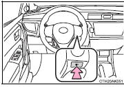
Items displayed can be switched by pressing the “DISP” switch.
■ Odometer
Displays the total distance the vehicle has been driven.
Except vehicles with a manual transmission: Press and hold the “DISP” switch to change the display to the Eco Driving Indicator Light customization screen. ■ Trip meter A*/trip meter B
* Displays the distance the vehicle has been driven since the meter was last reset. Trip meters A and B can be used to record and display different distances independently.
■ Current fuel consumption
Displays the current rate of fuel consumption.
Use the displayed current fuel consumption as a reference.
■ Average fuel consumption
* Displays the average fuel consumption since the function was reset.
• Use the displayed average fuel consumption as a reference.
• Except vehicles with a manual transmission: While the average fuel consumption is being displayed, the Eco Driving Indicator Zone Display is displayed.
■ Driving range
Displays the estimated maximum distance that can be driven with the quantity of fuel remaining.
• This distance is computed based on your average fuel consumption. As a result, the actual distance that can be driven may differ from that displayed.
• When only a small amount of fuel is added to the tank, the display may not be updated.
When refueling, turn the engine switch off. If the vehicle is refueled without turning the engine switch off, the display may not be updated.
■ Average vehicle spee
d Displays the average vehicle speed since the engine was last started.
*: Press and hold the “DISP” switch to reset.


Other materials:
Steering column
Service data
Torque specification
Power steering
Service data
Torque specification
: For use without sst ...
Overhaul
1. Drain clutch fluid
2. Disconnect clutch release cylinder to flexible hose tube
Using sst, disconnect the flexible hose tube.
Sst 09023–00100
Hint:
use a container to catch the fluid.
3. Remove clutch release cylinder assy
Remove the 3 bolts, clutch release cylinder assy ...
Inspection procedure
1 Check p/t squib(rh) circuit(airbag sensor assy center – front
seat outer belt assy rh)
Disconnect the negative (–) terminal cable from the battery,
and wait at least for 90 seconds.
disconnect the connectors between the airbag sensor
assy center and the seat belt pretensio ...