Toyota Corolla (E120) 2002–2008 Repair Manual / Diagnostics / Audio system / Sound quality is bad in all modes (volume is too low)
Toyota Corolla (E120): Sound quality is bad in all modes (volume is too low)
Wiring diagram
Inspection procedure
1 Adjust sound quality
- Adjust the sound quality.
- Operate the radio receiver assy to adjust the sound quality.
Standard: malfunction disappear.


2 Compare it with another car of same model
- Compare it with another vehicle of the same model.
- Compare with the vehicle of the same type which does not have a
trouble to see if there is any
difference in the condition of trouble occurrence.
Standard: no difference found.


3 Check harness and connector(between radio receiver assy and speaker)

4 Inspect front no.1 Speaker assy
- Preparation for check
- disconnect the connector of the speaker.
- resistance check
- check the resistance between the terminals of the speaker.
Notice
: the speaker should not be removed for checking.
Standard value: 4 Ω


5 Inspect front no.2 Speaker assy
- Check that malfunction disappear when a known good speaker is installed.
Standard: malfunction disappear.
Hint
: connect the all connectors of speakers.


6 Inspect rear speaker assy
- Preparation for check
- disconnect the connector of the speaker.
- resistance check
- check the resistance between the terminals of the speaker.
Notice
: the speaker should not be removed for checking.
Standard value: 6 Ω


7 Inspect radio receiver assy(+b, acc, gnd)
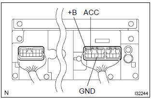
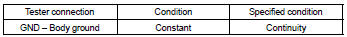
- Check that the continuity between terminals at each condition, as shown in the chart.
Standard:
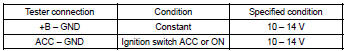
- Check that the voltage between terminals at each condition, as shown in the chart.
Standard:

Repair or replace harness or connector


Other materials:
Shift position uses
*: Shifting to the D position allows the system to select a gear suitable for
driving conditions. Setting the shift lever to the D position is recommended for
normal driving.
■Downshifting restrictions
The shift lever cannot be downshifted if the following speeds are exceeded.
mph (km ...
Optimal use of the multimedia system
On the “Sound Settings” screen, sound quality (Treble/Mid/ Bass), volume balance
can be adjusted.
How to adjust the sound settings and sound quality
1 2 3 Select “-” or “+” to adjust the treble, mid or bass to a level between
-5 and 5.
4 5 Select “Front” or “Rear” to adjus ...
Mechanical system tests
1. Perform mechanical system tests
Measure the stall speed.
The object of this test is to check the overall performance of the transaxle
and engine by measuring
the stall speeds in the d and r positions.
Notice:
Do the test at normal operating atf temperature 50 to 80 °c (122 to
...