Toyota Corolla (E120) 2002–2008 Repair Manual / Diagnostics / Audio system / No sound is heard from speaker in all modes
Toyota Corolla (E120): No sound is heard from speaker in all modes
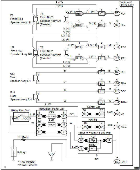
Wiring diagram
Inspection procedure
1 Check lcd (liquid crystal display) for lighting
- Lcd illumination check
- turn the ignition switch acc.
- Turn the radio receiver assembly on.
Standard: lcd illumination of the radio receiver assembly light.


2 Control fader and adjust sound balance
- Fader and balance adjustment
- operate the radio receiver assembly to adjust the fader and the balance to identify the speaker that does not sound.


3 Inspect front no.1 Speaker assy
- Preparation for check
- disconnect the connector of the speaker.
- resistance check
- check the resistance between the terminals of the speaker.
Notice
: the speaker should not be removed for checking.
Standard value: 4 Ω


4 Inspect front no.2 Speaker assy
- Check that malfunction disappear when a known good speaker is installed.
Standard: malfunction disappear.
Hint
: connect the all connectors of speakers.


5 Inspect rear speaker assy
- Preparation for check
- disconnect the connector of the speaker.
- resistance check
- check the resistance between the terminals of the speaker.
Notice
: the speaker should not be removed for checking.
Standard value: 6 w

6 Check harness and connector(between radio receiver assy and speaker)

Check and replace radio receiver assy
7 Inspect radio receiver assy(+b, acc, gnd)
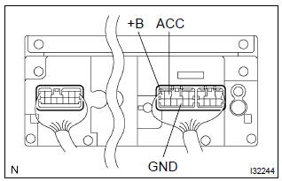
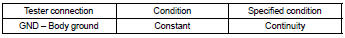
- Check that the continuity between terminals at each condition, as shown in the chart.
Standard:
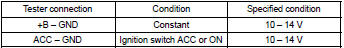
- Check that the voltage between terminals at each condition, as shown in the chart.
Standard:

Repair or replace harness or connector


Other materials:
Body panel anti-rust agent (wax) application areas
Apply rustop w to the doors and hood edges (tips of outer panel folded parts)
and undersides, areas around
hinges, etc.To prevent rust. Coat the undersides of the edges using a nozzle and
air gun, and coat the areas around
the hinges using a brush.
Hint:
if rustop is unnecessarily ...
Circuit description
Refer to dtc p0120
Dtc no.
Dtc detection condition
Trouble area
P0121
The following condition is met 4 times. After the vehicle speed
has exceeded 19 mph (30 km/h) once, the throttle position
sensor output value is out of normal range when the throttle
...
Inspection procedure
1 Check d squib circuit(airbag sensor assy center – horn button
assy)
Disconnect the negative (–) terminal cable from the battery,
and wait at least for 90 seconds.
disconnect the connectors between the airbag sensor
assy center and the horn button assy.
for the oran ...