
Toyota Corolla (E120): Inspection procedure
1 Check door lock
- When the door does not operate manually, proceed to ”a”.
- when the door does not operate via the key, proceed to ”b”.


2 Inspect door lock control switch
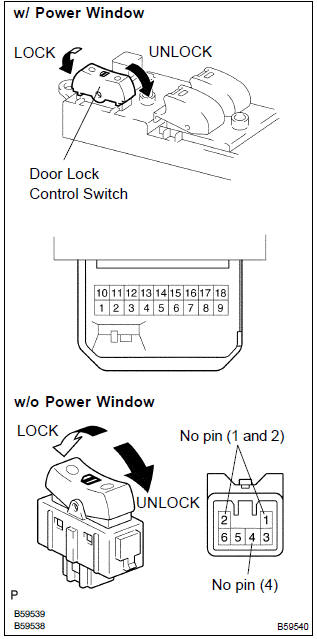
- W/ power window: remove the power window regulator master switch assy.
- Inspect the master switch (door lock control switch) continuity, as shown in the illustration and table.
Standard:

- W/o power window: remove the door lock control switch.
- Inspect the door lock control switch continuity, as shown in the illustration and table.
Standard:

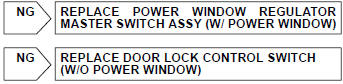

3 Check wire harness (switch integration relay)
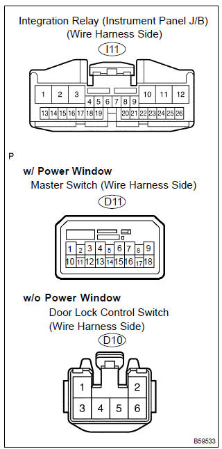
- W/ power window:
disconnect the power window regulator master switch
assy and integration relay connectors.
W/o power window: disconnect the door lock control switch and integration relay connectors.
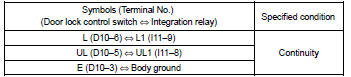
- check the continuity between the terminals of the power window regulator master switch assy or door lock control switch and integration relay connectors, as shown in the illustration and tables.
[W/ power window] standard (check for open):
![[W/o power window]](images/books/422/24/index.38.jpg)
[W/o power window] standard (check for open):
4 Inspect driver’s door lock
- Inspect the driver’s door lock key switch.
- inspect the driver’s door lock position switch.


5 Check wire harness (driver’s door lock integration relay)
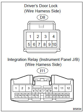
- Disconnect the driver’s door lock and integration relay connectors.
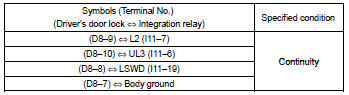
- check the continuity between the terminals of the driver’s door lock and integration relay connectors, as shown in the illustration and table.
Standard (check for open):


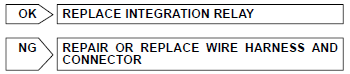
Replace integration relay


Other materials:
Selecting tire chains
Use the correct tire chain size when mounting the tire chains.
Chain size is regulated for each
tire size.
Side chain (0.12 in. [3 mm] in
diameter)
Side chain (0.39 in. [10 mm]
in width)
Side chain (1.18 in. [30 mm]
in length)
Cross chain (0.16 in. [4 mm]
in diameter)
Cross chain (0.55 i ...
Fuel information
You must only use unleaded gasoline in your vehicle.
Select octane rating 87 (Research Octane Number 91) or higher.
Use of unleaded gasoline with an octane rating lower than 87 may result in engine
knocking. Persistent knocking can lead to engine damage.
At minimum, the gasoline you use should ...
Cruise control
Preparation
Sst
Recomended tools
Equipment
...