Toyota Corolla (E120) 2002–2008 Repair Manual / Diagnostics / Power door lock control system / Key confinement prevention function does not work
properly (unlock warning switch circuit)
Toyota Corolla (E120): Key confinement prevention function does not work properly (unlock warning switch circuit)
Circuit description
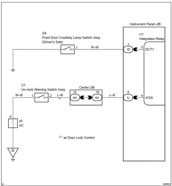
The unlock warning switch turns on when the key is inserted in the ignition key cylinder and the door courtesy switch turns on when the driver’s door is opened, and the integration relay monitors both switches conditions.
According to these switches conditions, the integration relay controls the door locking operation not to lock the doors while both switches are on, in order to prevent the key from being confined.
Wiring diagram
Inspection procedure
1 Inspect un–lock warning switch assy
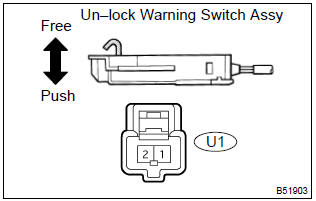
- Remove the un–lock warning switch assy.
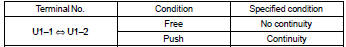
- inspect the un–lock warning switch assy continuity, as shown in the illustration and table.
Standard:


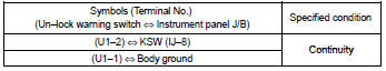
2 Check wire harness (un–lock warning switch instrument panel j/b)
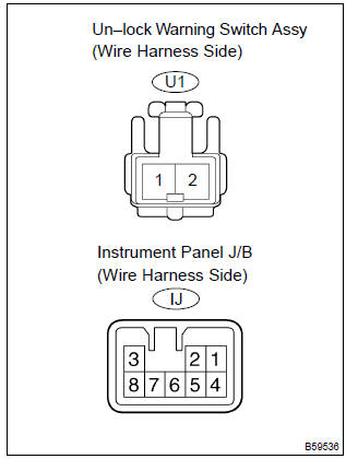
- Disconnect the un–lock warning switch assy and instrument panel j/b connectors.
- check the continuity between the terminals of the un–lock
warning switch assy and instrument panel j/b connectors,
as shown in the illustration and table.
Standard (check for open):

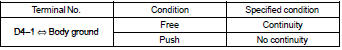
3 Inspect front door courtesy lamp switch assy (driver’s side)
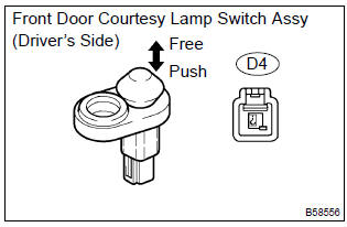
- Remove the courtesy lamp switch.
- inspect the courtesy lamp switch continuity, as shown in the illustration and table.
Standard:

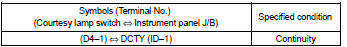
4 Check wire harness (front door courtesy lamp switch assy [driver’s side] instrument panel j/b)
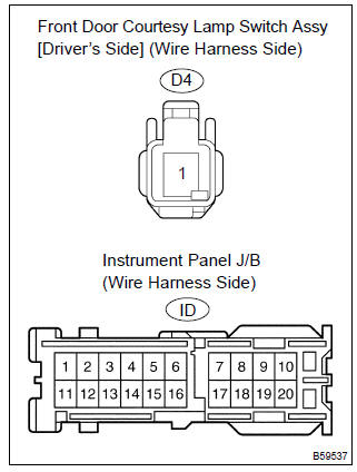
- Disconnect the courtesy lamp switch and instrument panel j/b connectors.
- check the continuity between the terminals of the courtesy lamp switch and instrument panel j/b connectors, as shown in the illustration and table.
Standard (check for open):

Replace integration relay


Other materials:
Problem symptoms table
If a normal code is displayed during the dtc check but the problem still
occurs, check the circuits for each
problem symptom in the order given in the table below and proceed to the
relevant troubleshooting page.
Notice:
when replacing skid control ecu, sensor or etc., Turn the ignition swi ...
If you think something is wrong
If you notice any of the following
symptoms, your
vehicle probably needs
adjustment or repair. Contact
your Toyota dealer as
soon as possible.
Visible symptoms
Fluid leaks under the vehicle.
(Water dripping from the air
conditioning after use is normal.)
Flat-looking tires or uneven
tire wear
...
Inspection procedure
1 Check operation(overdrive)
Drive the vehicle after the engine warms up.
check that overdrive on e off occurs by an operation of the o/d
switch on–off.
2 Inspect terminal voltage(od)
Remove the cruise control ecu assy with the connector
still connected.
tur ...