Toyota Corolla (E120) 2002–2008 Repair Manual / Diagnostics / Supplemental restraint system / Short in squib (2nd step) circuit (to
b+) / Inspection procedure
Toyota Corolla (E120): Inspection procedure
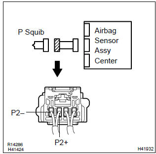
1 Check p squib circuit(airbag sensor assy center – instrument panel passenger airbag assy)
- Disconnect the negative (–) terminal cable from the battery, and wait at least for 90 seconds.
- disconnect the connector between the airbag sensor assy center and the instrument panel passenger airbag assy.
- connect the negative (–) terminal cable to the battery, and wait at least for 2 seconds.
- turn the ignition switch to on.
- for the connector (on the instrument panel passenger airbag assy side) between the airbag sensor assy center and the instrument panel passenger airbag assy, measure the voltage between p2+ and body ground.
Ok: voltage: below 1 v

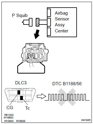
2 Check air bag sensor assy center
Sst 09843–18040
- Turn the ignition switch to lock.
- disconnect the negative (–) terminal cable from the battery, and wait at least for 90 seconds.
- connect the connector to the airbag sensor assy center.
- using a service wire, connect p2+ and p2– of the connector (on the instrument panel passenger airbag assy side) between the airbag sensor assy center and the instrument panel passenger airbag assy.
- connect the negative (–) terminal cable to the battery, and wait at least for 2 seconds.
- turn the ignition switch to on, and wait at least for 20 seconds.
- clear the dtc stored in memory .
- turn the ignition switch to lock, and wait at least for 20 seconds.
- turn the ignition switch to on, and wait at least for 20 seconds.
- check the dtc .
Ok: dtc b1188/56 is not output.
Hint
: codes other than code b1188/56 may be output at this time, but they are not relevant to this check.


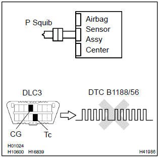
3 Check p squib
Sst 09843–18040
- Turn the ignition switch to lock.
- disconnect the negative (–) terminal cable from the battery, and wait at least for 90 seconds.
- connect the instrument panel passenger airbag assy connector.
- connect the negative (–) terminal cable to the battery, and wait at least for 2 seconds.
- turn the ignition switch to on, and wait at least for 20 seconds.
- clear the dtc stored in memory .
- turn the ignition switch to lock, and wait at least for 20 seconds.
- turn the ignition switch to on, and wait at least for 20 seconds.
- check the dtc .
Ok: dtc b1188/56 is not output.
Hint
: codes other than code b1188/56 may be output at this time, but they are not relevant to this check.

4 Use simulation method to check


Replace all srs components including the wire harness


Other materials:
Inspection procedure
1 Check d squib circuit(airbag sensor assy center – horn button
assy)
Disconnect the negative (–) terminal cable from the battery,
and wait at least for 90 seconds.
disconnect the connectors between the airbag sensor
assy center and the horn button assy.
release the airbag ...
Overhaul
Hint: components:
1. Drain manual transaxle oil (m/t transaxle)
torque: 39.2 Nvm (400 Kgf·cm, 29 ft·lbf)
2. Drain automatic transaxle fluid (a/t transaxle)
torque: 17.5 Nvm (178 Kgf·cm, 13 ft·lbf)
3. Remove front wheel
4. Remove engine under cover lh
5. Remove front axle hub lh nut
...
Selecting shift ranges in
the D position
To drive using temporary shift
range selection, operate the "-"
or "+" paddle shift switch.
When the "-" paddle shift switch
is operated, the shift range
switches to a range that enables
engine braking force that is suitable
to driving conditions. When
the "+" paddle shift switch is
operated, the s ...