Toyota Corolla (E120): Circuit description
The p squib (2nd step) circuit consists of the airbag sensor assy center and instrument panel passenger airbag assy.
It causes the srs to deploy when the srs deployment conditions are satisfied.
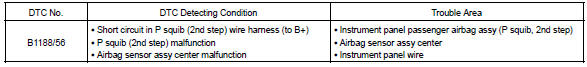
Dtc b1188/56 is recorded when a b+ short is detected in the p squib (2nd step) circuit.
Wiring diagram


Other materials:
Problem symptoms table
If a normal code is displayed during the dtc check but the problem still
occurs, check the circuits for each
problem symptom in the order given in the table below and proceed to the
relevant troubleshooting page.
Notice:
when replacing skid control ecu, sensor or etc., Turn the ignition swi ...
Engine rear oil seal
Replacement
1. Remove manual transaxle assy (m/t transaxle)
2. Remove automatic transaxle assy (a/t transaxle)
3. Remove clutch cover assy (m/t transaxle)
remove the 6 bolts and clutch cover.
4. Remove clutch disc assy (m/t transaxle)
5. Remove flywheel sub–assy (m/t transaxle ...
Overhaul
Hint:
installation is in the reveres order of the removal. But the
installation is indicated only when it has a
point.
In the rh side, work in the same procedure as in the lh side.
1. Remove rear armrest assy lh
Using a screwdriver, remove the rear armrest.
Hint:
tape the s ...