Toyota Corolla (E120) 2002–2008 Repair Manual / Starting & charging / Starting system
Toyota Corolla (E120): Starting system
Inspection
1. Inspect starter assy
Notice
: these tests must be performed within 3 to 5 seconds to prevent burnout of the coil.
- perform the pull–in test.
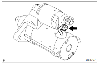
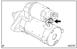
- Remove the nut, then disconnect the lead wire from terminal c.
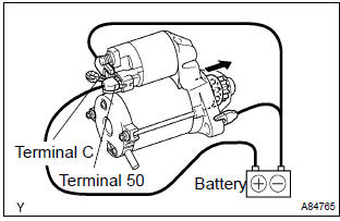
- Connect the battery to the starter repair service kit as shown in the illustration. Check that the clutch pinion gear is extended.
If the clutch pinion gear is not extended, replace the starter repair service kit.
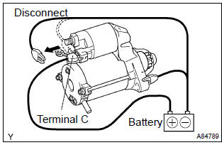
- Perform the hold–in test.
- Disconnect the negative (–) lead from terminal c
with the lead wire disconnected from terminal c.
Check that the clutch pinion gear remains extended.
If the clutch pinion gear returns, replace the starter repair service kit.
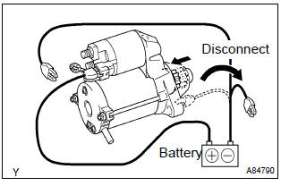
- Check the clutch pinion gear returns.
- Disconnect the negative (–) lead from the starter body. Check that the clutch pinion gear returns.
If the clutch pinion gear does not return, replace the starter repair service kit.
- Perform the no–load performance test.
- Connect the lead wire to terminal c with the nut.
Make sure that the lead is not grounded.
Torque: 10 nvm (102 Kgf·cm, 7 ft·lbf)
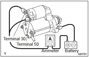
- Clamp the starter in a vise.
- Connect the battery and an ammeter to the starter as shown in the illustration.
- Check that the starter rotates smoothly and steadily
with the clutch pinion gear extended. Check that the
ammeter reads the specified current.
Specified current: 90 a or less at 11.5 V
If the current is not as specified, replace the starter repair service kit.
2. Inspect starter relay assy
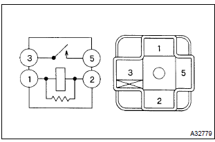
- Check the continuity.
- Using an ohmmeter, check for continuity between each terminal.
Specified condition:
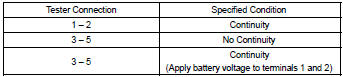
If the result is not as specified, replace the starter relay.


Other materials:
Circuit description
A flat type knock sensor (non–resonant type) has the structure that can
detect the vibration in a wider band
of frequency from about 6 khz to 15 khz and has the following features.
Knock sensors are fitted on the cylinder block to detect the engine knocking.
The sensor contains a piezoele ...
Diagnostic trouble code chart
Notice:
when removing the part, turn the ignition switch to off.
Hint:
using sst 09843–18040, it connect the terminal tc and cg of dlc3.
If any abnormality is not found when inspecting parts, inspect the ecu and
ground points for poor contact.
If a malfunction code is displayed during ...
Inspection procedure
1 Check p/t squib(lh) circuit(airbag sensor assy center – front seat
outer belt assy lh)
Disconnect the negative (–) terminal cable from the battery,
and wait at least for 90 seconds.
disconnect the connectors between the airbag sensor
assy center and the seat belt pretensio ...