Toyota Corolla (E120) 2002–2008 Repair Manual / Diagnostics / Supplemental restraint system / Short in d squib (2nd step) circuit / Inspection procedure
Toyota Corolla (E120): Inspection procedure
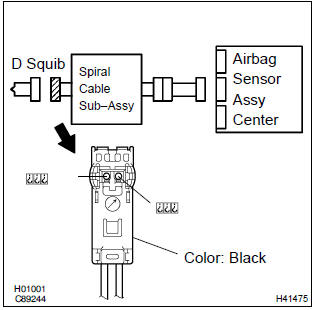
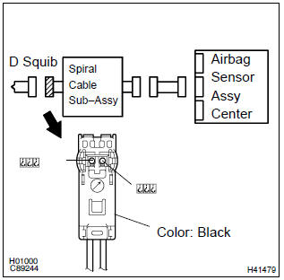
1 Check d squib circuit(airbag sensor assy center – horn button assy)
- Disconnect the negative (–) terminal cable from the battery, and wait at least for 90 seconds.
- disconnect the connectors between the airbag sensor assy center and the horn button assy.
- release the airbag activation prevention mechanism of the connector (on the airbag sensor assy center side) between the airbag sensor assy center and the spiral cable sub–assy .
- for the black connector (on the spiral cable sub–assy
side ) between the horn button assy and the spiral cable
sub–assy, measure the resistance between d2+ and
d2–.
Ok: resistance: 1 mw or higher


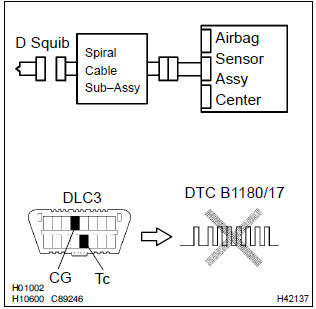
2 Check air bag sensor assy center
Sst 09843–18040
- Connect the connector to the airbag sensor assy center.
- connect the negative (–) terminal cable to the battery, and wait at least for 2 seconds.
- turn the ignition switch to on, and wait at least for 20 seconds.
- clear the dtc stored in memory .
- turn the ignition switch to lock, and wait at least for 20 seconds.
- turn the ignition switch to on, and wait at least for 20 seconds.
- check the dtc .
Ok: dtc b1180/17 is not output.
Hint
: codes other than code b1180/17 may be output at this time, but they are not relevant to this check.


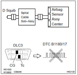
3 Check d squib
Sst 09843–18040
- Turn the ignition switch to lock.
- disconnect the negative (–) terminal cable from the battery, and wait at least for 90 seconds.
- connect the horn button assy connectors.
- connect the negative (–) terminal cable to the battery, and wait at least for 2 seconds.
- turn the ignition switch to on, and wait at least for 20 seconds.
- clear the dtc stored in memory .
- turn the ignition switch to lock, and wait at least for 20 seconds.
- turn the ignition switch to on, and wait at least for 20 seconds.
- check the dtc .
Ok: dtc b1180/17 is not output.
Hint
: codes other than code b1180/17 may be output at this time, but they are not relevant to this check.


Use simulation method to check
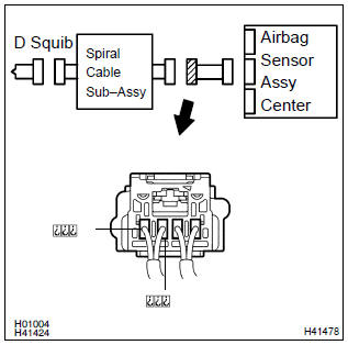
4 Check instrument panel wire(airbag sensor assy center – spiral cable sub–assy)
- Disconnect the connector of the instrument panel wire.
- release the airbag activation prevention mechanism of the connector (on the airbag sensor assy center side) between the airbag sensor assy center and the spiral cable sub–assy .
- for the connector (on the spiral cable sub–assy side) between
the airbag sensor assy center and the spiral cable
sub–assy, measure the resistance between d2+ and
d2–.
Ok: resistance: 1 mw or higher

5 Check spiral cable sub–assy
- Release the airbag activation prevention mechanism of the spiral cable sub–assy connector on the airbag sensor assy center side .
- for the black connector (on the spiral cable sub–assy
side) between the horn button assy and the spiral cable
sub–assy, measure the resistance between d2+ and
d2–.
Ok: resistance: 1 mw or higher


Use simulation method to check


Other materials:
Circuit description
Refer to dtc p0335
Dtc no.
Dtc detection condition
Trouble area
P0016
Deviation in crankshaft position sensor signal and camshaft
position sensor signal (2 trip detection logic)
Mechanical system (timing chain has jumped a tooth, chain
stretch ...
Timing gear cover oil seal
Replacement
1. Remove engine under cover rh
2. Remove front wheel rh
3. Remove fan and generator v belt
Turn the v–ribbed belt tensioner slowly clockwise and
loosen it. Then, remove the fan and generator belt v and
put back the v–ribbed belt tensioner little by little and fix
it ...
Luggage door hinge torsion bar rh
Replacement
Hint:
installation is in the reverse order of the removal. But the
installation is indicated only when it has a
point.
In the lh side, work in the same procedure as in the rh side.
Since the removal of the torsion bar will cause no tension, operation
of opening and closi ...