Toyota Corolla (E120) 2002–2008 Repair Manual / Diagnostics / Supplemental restraint system / Front airbag sensor (lh)
malfunction / Inspection procedure
Toyota Corolla (E120): Inspection procedure
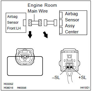
1 Check front airbag sensor (lh) circuit (to b+)(airbag sensor assy center – airbag sensor front lh)
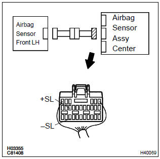
- Disconnect the negative (–) terminal cable from the battery, and wait at least for 90 seconds.
- disconnect the connectors between the airbag sensor assy center and the airbag sensor front lh.
- connect the negative (–) terminal cable to the battery, and wait at least for 2 seconds.
- ) turn the ignition switch to on.
- for the connector (on the airbag sensor assy center side)
between the airbag sensor front lh and the airbag sensor
assy center, measure the voltage between body ground
and each of +sl and –sl.
Ok: voltage: below 1 v


2 Check front airbag sensor(lh) circuit(to ground)(airbag sensor assy center – airbag sensor front lh)
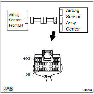
- Turn the ignition switch to lock.
- disconnect the negative (–) terminal cable from the battery, and wait at least for 90 seconds.
- for the connector (on the airbag sensor assy center side)
between the airbag sensor front lh and the airbag sensor
assy center, measure the resistance between body
ground and each of +sl and –sl.
Ok: resistance: 1 mΩ or higher


3 Check front airbag sensor (lh) circuit(open)(airbag sensor assy center – airbag sensor front lh)
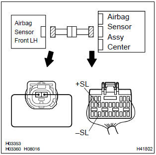
- Using a service wire, connect +sl and –sl of the connector (on the airbag sensor front lh side) between the airbag sensor assy center and the airbag sensor front lh.
- for the connector (on the airbag sensor assy center side)
between the airbag sensor front lh and the airbag sensor
assy center, measure the resistance between +sl and
–sl.
Ok: resistance: below 1 Ω


4 Inspect air bag sensor front lh
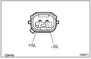
- For the connector of the airbag sensor front lh, measure
the resistance between +sl and –sl.
Ok: resistance: 820 Ω


5 Check air bag sensor assy center
Sst 09843–18040
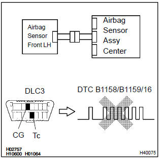
- Disconnect the negative (–) terminal cable from the battery, and wait at least for 90 seconds.
- connect the airbag sensor front lh connector and airbag sensor assy center connector.
- connect the negative (–) terminal cable to the battery, and wait at least for 2 seconds.
- turn the ignition switch to on, and wait at least for 20 seconds.
- clear the dtc stored in memory .
- turn the ignition switch to lock, and wait at least for 20 seconds.
- turn the ignition switch to on, and wait at least for 20 seconds.
- check the dtc .
Ok: dtc b1158/b1159/16 is not output.
Hint
: codes other than code b1158/b1159/16 may be output at this time, but they are not relevant to this check.


Use simulation method to check
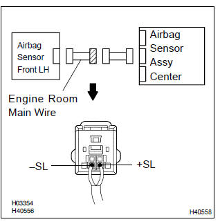
6 Check engine room main wire harness (to b+)(conector – airbag sensor front lh)
- Turn the ignition switch to lock.
- disconnect the negative (–) terminal cable from the battery, and wait at least for 90 seconds.
- disconnect the connector between the engine room main wire and the instrument panel wire.
- connect the negative (–) terminal to the battery, and wait at least for 2 seconds.
- turn the ignition switch to on.
- for the engine room main wire connector (on the airbag
sensor assy center side) between the airbag sensor assy
center and the airbag sensor front lh, measure the voltage
between body ground and each of +sl and –sl.
Ok: voltage: below 1 v

Repair or replace instrument panel wire
7 Check engine room main wire harness (to ground)(connector – airbag sensor front lh)
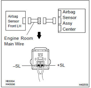
- Disconnect the connectors between the engine room main wire and the instrument panel wire.
- for the engine room main wire connector (on the airbag
sensor assy center side) between the airbag sensor assy
center and the airbag sensor front lh, measure the resistance
between body ground and each of +sl and –sl.
Ok: resistance: 1 mw or higher

Repair or replace instrument panel wire
8 Check engine room main wire harness(open)(connector – airbag sensor front lh)
- Disconnect the connectors between the engine room main wire and the instrument panel wire.
- using a service wire, connect +sl and –sl of the engine room main wire connector (on the airbag sensor front lh side) between the airbag sensor assy center and the airbag sensor front lh.
- for the engine room main wire connector (on the airbag
sensor assy center side) between the airbag sensor assy
center and the airbag sensor front lh, measure the resistance
between +sl and –sl.
Ok: resistance: below 1 Ω

Repair or replace instrument panel wire


Other materials:
Headlamp dimmer switch assy
Replacement
1. Remove steering column cover lwr
Remove 3 screws and steering column cover lwr.
2. Remove headlamp dimmer switch assy
Disconnect the connector.
release the claw and pull out the head light dimmer
switch assy.
...
Starting the engine
1 Check that the parking brake is set.
► Vehicles without a multi-information display
2 Continuously variable transmission: Check that the shift lever is set in P.
Firmly depress the brake pedal.
Manual transmission: Check that the shift lever is set in N. Firmly depress the
clutch peda ...
Shifting the shift lever
Vehicles without a smart key system:
While the engine switch is in the “ON” position, depress the brake pedal and
move the shift lever.
Vehicles with a smart key system: While the engine switch is in IGNITION ON mode,
depress the brake pedal and move the shift lever.
When shifting the ...