Toyota Corolla (E120) 2002–2008 Repair Manual / Front suspension / Front suspension arm sub–assy lower no.1 Lh
Toyota Corolla (E120): Front suspension arm sub–assy lower no.1 Lh
Replacement
Hint
: components:
1. Remove front wheel
2. Disconnect front stabilizer link assy lh (lh (a/t) position)
3. Disconnect front stabilizer link assy rh (lh (a/t) position)
Hint
: remove the rh side by the same procedures as the lh side.
4. Separate front suspension arm sub–assy lower no.1 Lh
- Remove the bolt and 2 nuts, and separate the front suspension arm sub–assy lower no.1 Lh from the lower ball joint assy front lh.
5. Separate front suspension arm sub–assy lower no.1 Rh (lh (a/t) position)
Hint
: remove the rh side by the same procedures as the lh side.
6. Separate rack & pinion power steering gear assy (lh (a/t) position)
- remove the 4 bolts, separate the rack & pinion power steering gear
assy.
Notice
: loosen the bolt since the nut cannot be rotated.
- suspend the rack & pinion power steering gear assy.
7. Suspend engine assy (lh (a/t) position)
8. Separate front suspension crossmember sub–assy (lh (a/t) position)
- Remove the 3 bolts and 3 nuts, disconnect the transverse engine engine mounting insulator and engine mounting member sub–assy center from the front suspension crossmember sub–assy.
- Remove the 4 bolts.
- lower the transmission jack, remove the front suspension crossmember sub–assy.
9. Remove front suspension arm sub–assy lower no.1 Lh
- Remove the 2 bolts, nut and front suspension arm sub– assy lower no.1 Lh from the front suspension crossmember sub–assy.
10. Temporary tighten front suspension arm sub–assy lower no.1 Lh
- Install the front suspension arm sub–assy lower no. 1 Lh, temporarily tighten the 2 bolts and nut.
11. Install front suspension crossmember sub–assy (lh (a/t) position)
- lift the front suspension crossmember sub–assy up with a transmission jack.
- Insert sst to the base hole of the rh side crossmember
and rh side of the vehicle.
Sst 09670–00010
- tighten the bolt temporarily in the order a and b.
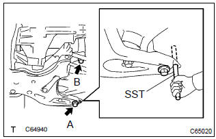
- Insert sst to the base hole of the lh side of crossmember
and lh side of the vehicle.
Sst 09670–00010
- tighten the bolt temporarily in the order a and b.
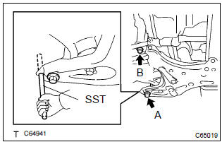
- insert sst to the base hole of the rh side of crossmember
and rh side of the vehicle.
Sst 09670–00010
- Then tighten the bolt a and b by the specified torque.
Torque:
bolt a: 157 nvm (1,601 Kgf·cm, 116 ft·lbf) bolt b: 113 nvm (1,152 Kgf·cm, 83 ft·lbf) - insert sst to the base hole of the lh side of crossmember
and lh side of the vehicle.
Sst 09670–00010
- tighten the bolt a and b by the specified torque.
Torque:
bolt a: 157 nvm (1,601 Kgf·cm, 116 ft·lbf) bolt b: 113 nvm (1,152 Kgf·cm, 83 ft·lbf)
- Connect the transverse engine engine mounting insulator and engine mounting member sub–assy center to the front suspension crossmember sub–assy.
- install the 3 bolts and 3 nuts.
Torque: 52 nvm (530 Kgf·cm, 38 ft·lbf)
12. Install rack & pinion power steering gear assy (lh (a/t) position)
- install the rack & pinion power steering gear assy with the 4
bolts.
Torque: 58 nvm (591 Kgf·cm, 43 ft·lbf)
13. Install front suspension arm sub–assy lower no.1 Lh
- Install the front suspension arm sub–assy lower no.1 Lh
with the 2 nuts and bolt to the lower ball joint assy front lh.
Torque: 89 nvm (908 Kgf·cm, 66 ft·lbf)
14. Install front suspension arm sub–assy lower no.1 Rh (lh (a/t) position)
Hint
: install the rh side by the same procedures as the lh side.
15. Install front stabilizer link assy lh (lh (a/t) position)
16. Install front stabilizer link assy rh (lh (a/t) position)
Hint
: install the rh side by the same procedure as the lh side.
17. Stabilize suspension
- install the front wheel and jack down the vehicle.
Torque: 103 nvm (1,050 Kgf·cm, 76 ft·lbf)
- bounce the vehicle up and down several times to stabilize the suspension.
18. Fully tighten front suspension arm sub–assy lower no.1 Lh
- Fully tighten the 2 bolts and nut.
Torque: 137 nvm (1,397 Kgf·cm, 101 ft·lbf)
Notice
: tighten the bolt since the nut cannot be rotated.
19. Inspect and adjust front wheel alignment


Other materials:
Although system is powered,cd cannot be played
Wiring diagram
Inspection procedure
1 Check if a proper cd is inserted
Check that a proper cd is inserted.
Make sure that the cd is a normal audio cd, and that there is no
deformation, flaw, stain, burr
and other defects on the cd.
Standard: normal audio cd.
Reference:
...
Brake fluid
Bleeding
Notice:
wash the brake fluid off immediately if it comes into contact with any painted
surface.
Hint:
if any work is done on the brake system or if air in the brake lines is
suspected, bleed the air from the system.
1. Fill reservoir with brake fluid
fluid: sae j1703 or fmvss no. ...
Circuit description
Refer to dtc p0130
Hint:
the ecm provides a pulse width modulated control circuit to adjust current
through the heater. The heated
oxygen sensor heater circuit uses a relay on the b+ side of the circuit.
Monitor description
The ecm uses the heated oxygen sensor information to regulate t ...