Toyota Corolla (E120) 2002–2008 Repair Manual / Front suspension / Lower ball joint assy front lh
Toyota Corolla (E120): Lower ball joint assy front lh
Replacement
Hint
: components:
1. Inspect lower ball joint assy front lh

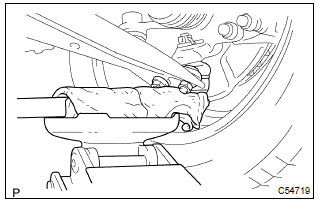
- Jack up front side of the vehicle.
- check the rattle of the lower ball joint assy front lh.
2. Remove front wheel
3. Remove front axle hub lh nut sst 09930–00010
4. Disconnect speed sensor front lh (w/ abs)
5. Separate tie rod end sub–assy lh sst 09628–62011
6. Separate front suspension arm sub–assy lower no.1 Lh
7. Separate front axle assy lh
8. Remove lower ball joint assy front lh

- Remove the cotter pin and castle nut.
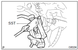
- using sst, remove the lower ball joint assy from the
steering knuckle lh.
Sst 09628–62011
9. Inspect lower ball joint assy front lh

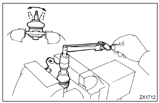
- As shown in the illustration, flip the ball joint stud back and forth 5 times, before installing the nut.
- using a torque wrench, turn the nut continuously at a rate
of 3 – 5 seconds per 1 turn and take the torque reading
on the 5th turn.
Turning torque: 0.98 – 4.9 Nvm (10 – 50 Kgf·cm, 8.7 – 43 In.Vlbf)
10. Install lower ball joint assy front lh
- install the lower ball joint assy front lh to the steering knuckle
lh, tighten the castle nut.
Torque: 103 nvm (1050 Kgf·cm, 76 ft·lbf)
- install a new cotter pin.
11. Install front axle assy lh
12. Install front suspension arm sub–assy lower no.1 Lh
13. Install tie rod end sub–assy lh
14. Install speed sensor front lh (w/ abs)
15. Install front axle hub lh nut sst 09931–00020
16. Install front wheel torque: 103 nvm (1,050 Kgf·cm, 76 ft·lbf)
17. Inspect and adjust front wheel alignment
18. Check abs speed sensor signal (w/ abs)
Other materials:
Steering wheel audio switches
Some audio features can be controlled using the switches on the steering wheel.
Operation may differ depending on the type of multimedia system or navigation
system. For details, refer to the manual provided with the multimedia system or
navigation system.
Operating the multimedia system using ...
Components
...
Lubrication system
*: The engine oil capacity is a reference quantity to be used when changing the
engine oil. Warm up and turn off the engine, wait more than 5 minutes, and check
the oil level on the dipstick.
■ Engine oil selection
“Toyota Genuine Motor Oil” is used in your Toyota vehicle. Use Toyo ...


