Toyota Corolla (E120) 2002–2008 Repair Manual / Diagnostics / Supplemental restraint system / Short in p squib circuit (to b+) / Circuit description
Toyota Corolla (E120): Circuit description
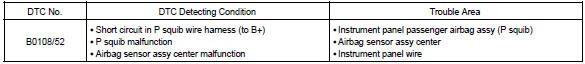
The p squib circuit consists of the airbag sensor assy center and instrument panel passenger airbag assy.
It causes the srs to deploy when the srs deployment conditions are satisfied.
Dtc b0108/52 is recorded when a b+ short is detected in the p squib circuit.
Wiring diagram


Other materials:
Front door belt moulding assy lh
Replacement
Hint:
the installation procedures are the removal procedures in reverse
order.
Use the same procedures for the rh side and lh side.
1. Remove front armrest assy lh
2. Remove power window regulator master switch assy (w/ power window)
3. Remove front armrest base panel up ...
Switching the display
Press to display or hide the album
title.
If there is additional text, is
displayed.
Press and hold to display the remaining
text.
■USB memory functions
●Depending on the USB memory that is connected to the system, the device itself
may not be operable and certain function ...
On–vehicle inspection
1. Inspect front axle hub bearing
remove the front wheel.
separate the front disc brake caliper assy .
remove the front disc.
inspect the bearing backlash.
Using a dial indicator, check the backlash near the
center of the axle hub.
Maximum: 0.05 Mm (0. ...