Toyota Corolla (E120) 2002–2008 Repair Manual / Diagnostics / Supplemental restraint system / Short in p squib circuit (to b+) / Inspection procedure
Toyota Corolla (E120): Inspection procedure
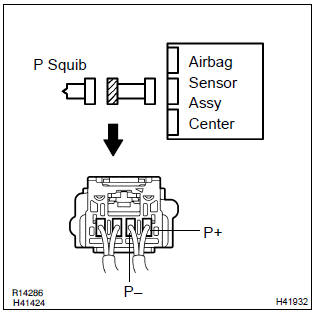
1 Check p squib circuit(airbag sensor assy center – instrument panel passenger airbag assy)
- Disconnect the negative (–) terminal cable from the battery, and wait at least for 90 seconds.
- disconnect the connectors between the airbag sensor assy center and the instrument panel passenger airbag assy.
- connect the negative (–) terminal cable to the battery, and wait at least for 2 seconds.
- turn the ignition switch to on.
- for the connector (on the instrument panel passenger airbag
assy side) between the airbag sensor assy center
and the instrument panel passenger airbag assy, measure
the voltage between p+ and body ground.
Ok: voltage: below 1 v

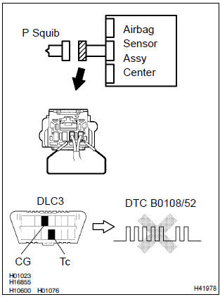
2 Check air bag sensor assy center
Sst 09843–18040
- Turn the ignition switch to lock.
- disconnect the negative (–) terminal cable from the battery, and wait at least for 90 seconds.
- connect the connector to the airbag sensor assy center.
- using a service wire, connect p+ and p– of the connector (on the instrument panel passenger airbag assy side) between the airbag sensor assy center and the instrument panel passenger airbag assy.
- connect the negative (–) terminal cable to the battery, and wait at least for 2 seconds.
- turn the ignition switch to on, and wait at least for 20 seconds.
- clear the dtc stored in memory .
- turn the ignition switch to lock, and wait at least for 20 seconds.
- turn the ignition switch to on, and wait at least for 20 seconds.
- check the dtc .
Ok: dtc b0108/52 is not output.
Hint
: codes other than code b0108/52 may be output at this time, but they are not relevant to this check.


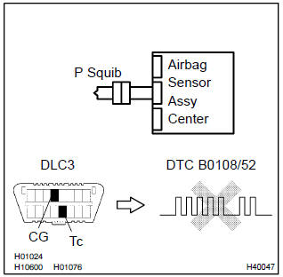
3 Check p squib
Sst 09843–18040
- Turn the ignition switch to lock.
- disconnect the negative (–) terminal cable from the battery, and wait at least for 90 seconds.
- connect the instrument panel passenger airbag assy connector.
- connect the negative (–) terminal cable to the battery, and wait at least for 2 seconds.
- turn the ignition switch to on, and wait at least for 20 seconds.
- clear the dtc stored in memory .
- turn the ignition switch to lock, and wait at least for 20 seconds.
- turn the ignition switch to on, and wait at least for 20 seconds.
- check the dtc .
Ok: dtc b0108/52 is not output.
Hint
: codes other than code b0108/52 may be output at this time, but they are not relevant to this check.

4 Use simulation method to check


Replace all srs components including the wire harness


Other materials:
Definition of terms
Term
Definition
Monitor description
Description of what the ecm monitors and how it detects malfunction
(monitoring purpose and its details).
Related dtcs
Diagnostic code
Typical enabling condition
Preconditions that allow the ecm to detect m ...
Symptom simulation
Hint:
the most difficult case in troubleshooting is when no symptoms occurs. In such
cases, a thorough customer
problem analysis must be carried out. Then the same or similar conditions and
environment in which the
problem occurred in the customer’s vehicle should be simulated. No matter ho ...
Checking the engine coolant
The coolant level is satisfactory
if it is between the "MAX" and
"MIN" lines on the reservoir
when the engine is cold.
Reservoir
"MAX" line
"MIN" line
If the level is on or below the "MIN"
line, add coolant up to the "MAX"
line.
■Coolant selection
Only use "Toyota Super Long Life
Coolant" or ...