Toyota Corolla (E120) 2002–2008 Repair Manual / Diagnostics / Supplemental restraint system / Short in d squib circuit / Circuit description
Toyota Corolla (E120): Circuit description
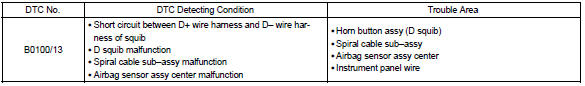
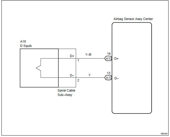
The d squib circuit consists of the airbag sensor assy center, spiral cable sub–assy and horn button assy.
It causes the srs to deploy when the srs deployment conditions are satisfied.
Dtc b0100/13 is recorded when a short is detected in the d squib circuit.
Wiring diagram


Other materials:
Malfunction in water temperature receiver gauge
Wiring diagram
Inspection procedure
1 Read value of hand–held tester
Check output value of ecm.
Connect the hand–held tester to dlc3.
Turn the ignition switch to on and push the hand–held tester main
switch on.
Select the data list mode on the hand–he ...
Under hood
General maintenance
1. General notes
maintenance requirements vary depending on the country.
Check the maintenance schedule in the owner’s manual supplement.
Following the maintenance schedule is mandatory.
Determine the appropriate time to service the vehicle using either miles
driv ...
Inspection procedure
1 Check source voltage
Measure the voltage of the battery.
Ok:
voltage: 10 – 14 v
2 Check air bag sensor assy center
Disconnect the negative (–) terminal cable from the battery, and wait at
least for 90 seconds.
disconnect the connectors from the airbag sensor assy ...