Toyota Corolla (E120) 2002–2008 Repair Manual / Diagnostics / Sfi system / Camshaft position sensor ”a”
circuit / Circuit description
Toyota Corolla (E120): Circuit description
The camshaft position sensor (g22+ signal) consists of a magnet, iron core and pickup coil.
The g22+ signal plate has 3 teeth on its outer circumference and is installed on the camshaft timing pulley.
When the camshafts rotate, the protrusion on the signal plate and the air gap on the pickup coil changes, causing fluctuations in the magnetic field and generating an electromotive force in the pickup coil.
The ne+ signal plate (crankshaft timing pulley) has 34 teeth and is installed to the crankshaft. The ne+ signal sensor generates 34 signals at every engine revolution. The ecm detects the crankshaft angle and the engine revolution based on the ne+ signals, and the cylinder and the angle of the vvt based on the combination of the g22+ and ne+ signals.
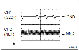
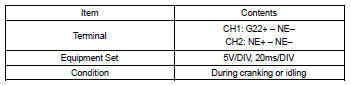
Reference: inspection using the oscilloscope.
Hint
: the correct waveform is as shown on the left.
Monitor description
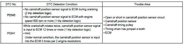
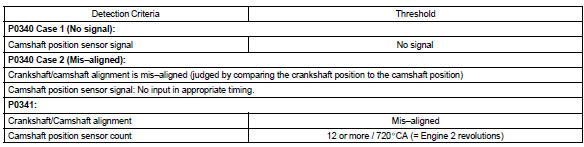
If there is no signal from the camshaft position sensor despite the engine revolving, or if the rotation of the camshaft and the crankshaft is not synchronized, the ecm interprets this as a malfunction of the sensor.
Monitor strategy
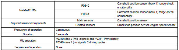
Typical enabling conditions
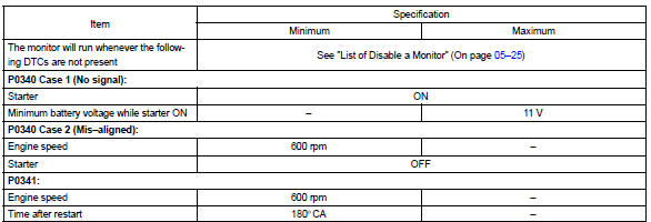
Typical malfunction thresholds
Component operating range

Wiring diagram
Refer to dtc p0335


Other materials:
How to scroll
: Select to scroll to the next or
previous page.
: If
appears to the right of titles, the
complete titles are too long for the display. Select this button to scroll the title.
Turn the “TUNE/SCROLL” knob to move the cursor box to select a desired item from
the list, and press the â ...
Replacement
Hint: components:
1. Precaution
2. Disconnect battery negative terminal
3. Remove horn button assy
Place the front wheels facing straight ahead.
using a torx socket wrench (t30), loosen the 2 torx
screws until the groove along the screw circumference
catches on the screw ca ...
Transmission valve body assy (atm)
Replacement
1. Remove engine under cover lh
2. Drain automatic transaxle fluid
remove the drain plug, gasket and drain atf.
install a new gasket and drain plug.
Torque: 17.5 Nvm (178 Kgf·cm, 13 ft·lbf)
3. Remove automatic transaxle oil pan sub–assy
Remove the 18 ...