Toyota Corolla (E120) 2002–2008 Repair Manual / Diagnostics / Sfi system / Camshaft position sensor ”a”
circuit / Inspection procedure
Toyota Corolla (E120): Inspection procedure
Hint
: read freeze frame data using the hand-held tester or the obd ii scan tool. Freeze frame data records the engine conditions when a malfunction is detected. When troubleshooting, it is useful for determining whether the vehicle was running or stopped, the engine was warmed up or not, the air–fuel ratio was lean or rich, etc. At the time of the malfunction.
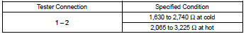
1 Inspect camshaft position sensor(resistance)
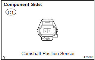
- Measure the resistance between the terminals of camshaft position sensor connector.
Standard:
Notice
: ”cold” and ”hot” shown above mean the temperature of the coils themselves. ”Cold” is from –10 c (14 f) to 50 c (122 f) and ”hot” is from 50 c (122 f) to 100 c (212 f).


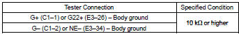
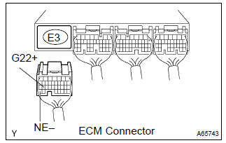
2 Check harness and connector(camshaft position sensor – ecm)
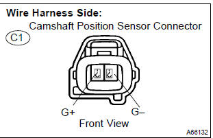
- Disconnect the c1 camshaft position sensor connector.
- disconnect the e3 ecm connector.
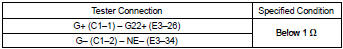
- check the resistance between the wire harness side connectors.
Standard (check for open):
Standard (check for short):
- Reconnect the ecm connector.
- reconnect the camshaft position sensor connector.

3 Check sensor installation(camshaft position sensor)
- Check the camshaft position sensor installation.


4 Check camshaft timing gear assy(teeth of plate)
- Check the teeth of the signal plate.


Replace ecm


Other materials:
Horn
To sound the horn, press on or close to the
mark.
CAUTION
■Caution while driving
Do not adjust the steering wheel while driving.
Doing so may cause the driver to mishandle the vehicle and cause an accident,
resulting in death or serious injury.
■After adjusting the steering wh ...
Replacement
1. Remove battery
2. Remove battery carrier
Remove the 4 bolts and battery carrier.
3. Disconnect floor shift cable transmission control shift
Remove the nut from the control shaft lever.
disconnect the control cable from the control shaft lever.
remove the clip a ...
On–vehicle inspection
1. Inspect air–fuel ratio compensation system
Hint:
you can also check the system by choosing ”data monitor”,
then ”o2 sensor output voltage” on the monitor of the
hand–held tester.
Connect the hand–held tester to the terminal 23 (ox1a)
@ 7 (e1) and 21 (ox1b) @ 7 (e1) of ...