Toyota Corolla (E120) 2002–2008 Repair Manual / Diagnostics / Sfi system / Random/multiple cylinder misfire
detected / Circuit description
Toyota Corolla (E120): Circuit description
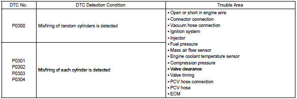
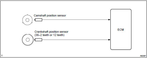
When a misfire occurs in the engine, hydrocarbons (hc) enter the exhaust in high concentrations. If this hc concentration is high enough, there could be an increase in exhaust emissions levels. High concentrations of hc passing through the catalyst also cause to temperature of the catalyst to increase, possibly damaging the catalyst. To prevent this increase in the emissions and limit the possibility of thermal damage, the ecm monitors the misfire rate. When the temperature of the catalyst reaches a point of thermal degradation, the ecm will blink the mil. For monitoring misfire, the ecm uses both the camshaft position sensor and crankshaft position sensor. The camshaft position sensor is used to identify misfiring cylinders and the crankshaft position sensor is used to measure variations in the crankshaft rotation speed. The misfire counter increments when crankshaft rotation speed variations exceed threshold values.
The ecm illuminates the mil if the misfiring rate exceeds a threshold value and could cause emissions deterioration.
Hint
: when codes for a misfiring cylinder are recorded repeatedly but no random misfire code is recorded, it indicates that the misfires have been detected and recorded at different times.
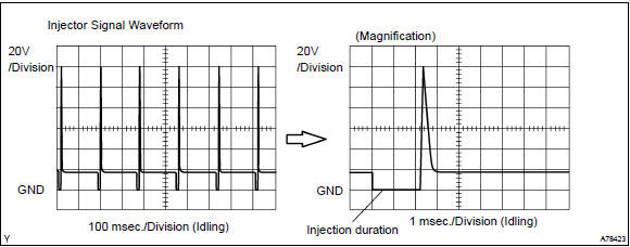
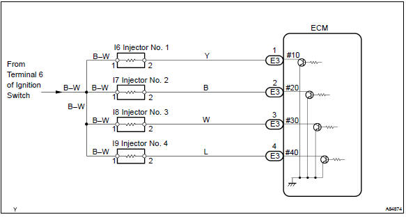
Reference: inspection using oscilloscope with the engine idling, check the waveform between terminals #10 to #40 and e01 of the ecm connectors.
Hint
: the correct waveform is as shown.
Monitor description
The ecm illuminates the mil if the misfiring rate exceeds a threshold value and could cause emissions deterioration.
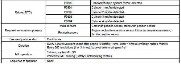
The ecm will illuminate the mil when the percent misfire exceeds the specified limit per 1,000 engine revolutions.
One occurrence of excessive misfire during engine start will set the mil. Four occurrences are required to set the mil 1,000 revolutions after engine start. (2 Trip detection logic) the mil blinks when ”percent misfire causing catalyst damage” per 200 revolution met 3 times (1 time if the engine rpm is in high speed range). (Mil blinks immediately)
Monitor strategy
Typical enabling conditions
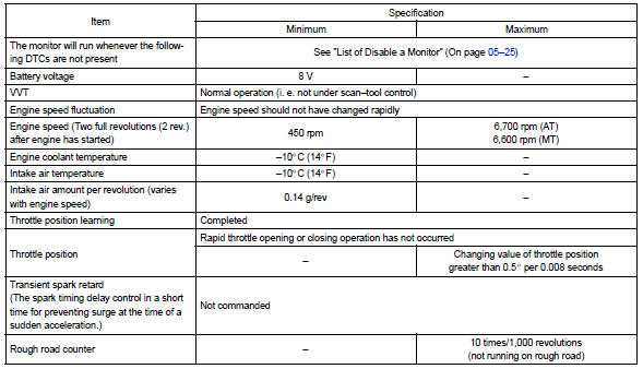
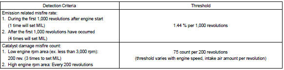
Typical malfunction thresholds
Wiring diagram
Refer to dtc p0351 for the wiring diagram of the ignition system.


Other materials:
Circuit description
The seat position sensor circuit consists of the airbag sensor assy center
and seat position sensor.
Dtc b1153/25 is recorded when a malfunction is detected in the seat position
sensor circuit.
Wiring diagram
...
Oxygen / af sensor heater monitor
Preconditions
The monitor will not run unless:
mil is off
drive pattern
connect the obd ii scan tool to the dlc3 to check monitor status
and preconditions.
Start the engine and allow it to idle for 9 minutes.
Drive the vehicle at 25 mph (40 km ...
Other functions
■ Switching between outside air and recirculated air modes
Press .
The mode switches between outside air mode (indicator off) and recirculated air
mode (indicator on) each time is pressed.
■ Defogging the windshield
Defoggers are used to defog the windshield and front side windows ...