Toyota Corolla (E120) 2002–2008 Repair Manual / Diagnostics / Sfi system / Throttle/pedal position
sensor/switch ”a” circuit / Circuit description
Toyota Corolla (E120): Circuit description
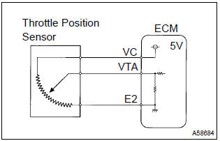
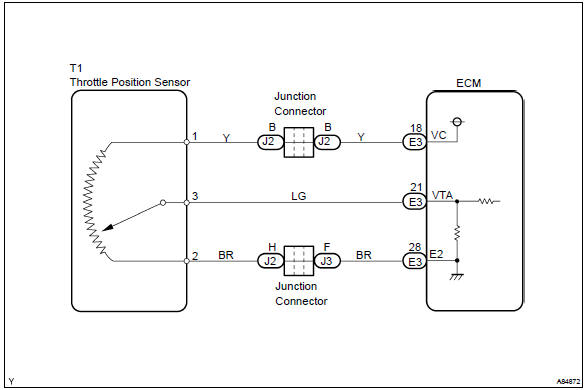
The throttle position sensor is mounted in the throttle body and detects the throttle valve opening angle.
When the throttle valve is fully closed, a voltage of approximately 0.3 To 1.0 V is applied to terminal vta of the ecm. The voltage applied to terminal vta of the ecm increases in proportion to the opening angle of the throttle valve and becomes approximately 3.2 To 4.9 V when the throttle valve is fully opened. The ecm judges the vehicle driving conditions from these signals input from terminal vta, uses them as one of the conditions for deciding the air–fuel ratio correction, power increase correction and fuel–cut control etc.
Hint
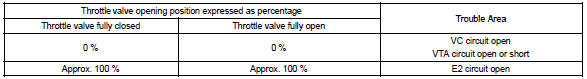
: after confirming dtcs, confirm the throttle valve opening percentage and closed throttle position switch condition using the hand–held tester or the obd ii scan tool.
Monitor description
The throttle position sensor varies its resistance with the throttle valve angle. The ecm applies a regulated reference voltage to the throttle position sensor “+: vc” terminal and calculates the angle of the throttle valve based on the voltage present at the throttle position sensor “signal: vta” terminal.
When the throttle valve is near the fully closed position, the output voltage of the throttle position sensor is low. When it is near the fully open position, the output voltage is high.
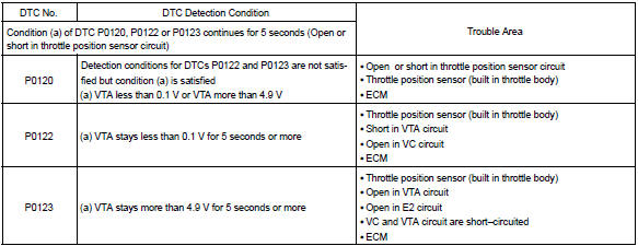
If the ecm detects that the output voltage of the throttle position sensor is out of the normal range, the ecm interprets this as a malfunction in the throttle position sensor and sets a dtc.
Monitor strategy
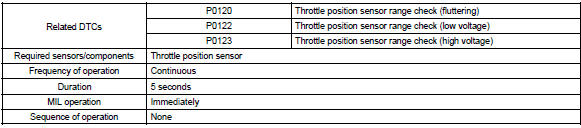
Typical enabling condition

Typical malfunction thresholds
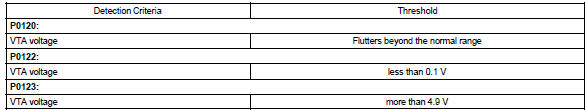
Component operating range

Wiring diagram


Other materials:
Using a top tether anchorage
(for Puerto Rico)
■ Top tether anchorages
Top tether anchorages are provided
for each rear seat.
Use top tether anchorages
when fixing the top strap.
Top tether anchorages
Top strap
■ Fixing the top strap to the
top tether anchorages
Install the child restraint system
in accordance to the operation
manual e ...
Entire combination meter does not operate
Wiring diagram
Inspection procedere
1 Check fuse
Check that continuity exists of dome fuse.
check that continuity exists of gauge fuse.
check that continuity exists of am1 fuse.
2 Inspect combination meter assy
Check continuity.
Disconnect the ” ...
Using the audio system
Optimal use of the audio system
Sound quality (treble/bass) and volume balance can be adjusted.
1 Displays the current mode
2 Changes the following setting
• Sound quality and volume balance
The sound quality and balance setting can be changed to produce the best sound.
• Automatic ...