Toyota Corolla (E120): Circuit description
The purpose of this circuit is to prevent the engine from stalling while driving in lock–up condition, when brakes are suddenly applied.
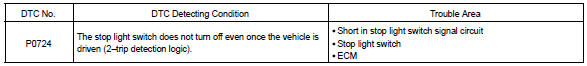
When the brake pedal is depressed, this switch sends a signals to the ecm. Then the ecm cancels the operation of the lock–up clutch while braking is in progress.
Monitor description
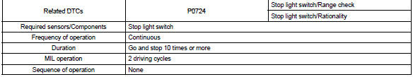
The circuit prevents the engine from stopping when the vehicle is stopped by sudden braking when the torque converter clutch is in the ”lock–up” mode. The ecm receives the signal from the stop light switch at the time brake pedal is depressed. Then, the ecm sends the signal to the lock–up solenoid valve not to be in lock–up condition. When the stop light switch remains on during ”stop and go” driving, the ecm interprets this as a fault in the stop light switch and the mil comes on. The vehicle must stop and go (3 km/h (2 mph) to 30 km/h (19 mph)) ten times for two driving cycles in order to detect malfunction.
Monitor strategy
Typical enabling condition
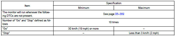
Typical malfunction thresholds

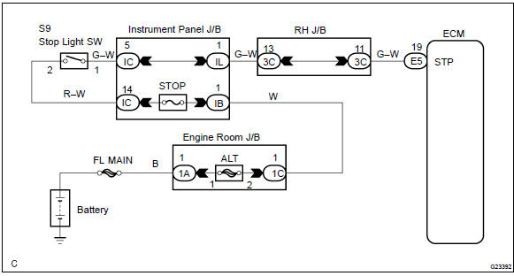
Wiring diagram


Other materials:
General information
There are many ecu controlled systems used in the corolla. In general, ecu
controlled system are considered
to be very intricate and require a high level of technical knowledge and expert
skill to troubleshoot.
The fact is, however, that if you proceed by inspecting the circuits one by one, ...
Inspection procedure
1 Check p/t squib(lh) circuit(airbag sensor assy center – front seat
outer belt assy lh)
Disconnect the negative (–) terminal cable from the battery,
and wait at least for 90 seconds.
disconnect the connectors between the airbag sensor
assy center and the seat belt pretensio ...
Inspection procedure
1 Check operation(stop lamp swtich assy)
Check that the stop light comes on when the brake pedal is depressed,
and turns off when the brake
pedal is released.
2 Input signal check
See input signal check on page 05–745.
check the indicator light when the brake pedal ...