Toyota Corolla (E120): Inspection
1. Windshield wiper switch assy
- Continuity check
- check the continuity of each terminal of the connector.
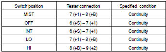
Front wiper switch
Standard:
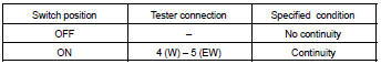
Front washer switch
Standard:
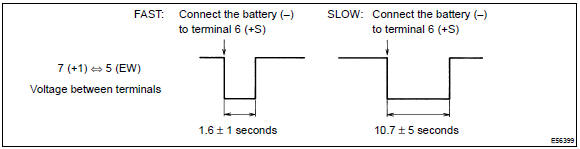
- W/o intermittent time adjust: intermittent operation check
- connect the voltmeter (+) terminal to terminal 7 (+1) of the connector, the voltmeter (–) terminal to terminal 5 (ew) of the connector.
- Connect the battery (+) to terminal 8 (+b) of the connector, the battery (–) to terminal 5 (ew) and 6 (+s) of the connector.
- Turn the wiper switch to the int position.
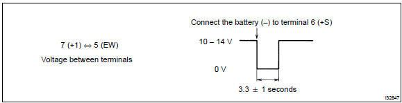
- Connect the battery (+) to terminal 6 (+s) of the connector for 5 seconds.
- Connect the battery (–) to terminal 6 (+s) of the connector.
Operate the intermittent wiper relay and check voltage between terminal 7 (+1) and terminal 5 (ew).
- W/ intermittent time adjust: intermittent operation check
- connect the voltmeter (+) terminal to terminal 7 (+1) of the connector, the voltmeter (–) terminal to terminal 5 (ew) of the connector.
- Connect the battery (+) to terminal 8 (+b) of the connector, the battery (–) to terminal 5 (ew) and 6 (+s) of the connector.
- Turn the wiper switch to the int position.
- Connect the battery (+) to terminal 6 (+s) of the connector for 5 seconds.
- Connect the battery (–) to terminal 6 (+s) of the connector.
Operate the intermittent wiper relay and check voltage between terminal 7 (+1) and terminal 5 (ew).
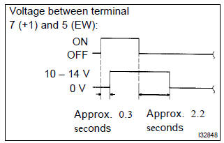
- Operation check (washer switch)
- turn the wiper switch to the off position.
- Connect the battery (+) to terminal 8 (+b) of the connector, the battery (–) to terminal 6 (+s) and 5 (ew) of the connecter.
- Connect the voltmeter (+) terminal to terminal 7 (+1)
of the connector, the voltmeter (–) terminal to terminal
5 (ew) of the connector. Turn the washer switch
to on and off and check voltage between terminal
7 (+1) and terminal 5 (ew).
Standard: see the illustration.
2. Windshield wiper motor assy
- Lo operation check
- connect the battery (+) to terminal 1 (+1) of the connector, the battery (–) to terminal 5 (e) of the connector, and check that the motor operates at low speed (lo).
- hi operation check
- connect the battery (+) to terminal 4 (+2) of the connector, the battery (–) to terminal 5 (e) of the connector, and check that the motor operates at high speed (hi).
- automatic stop operation check
- connect the battery (+) to terminal 1 (+1) of the connector,
the battery (–) to terminal 5 (e) of the connector.
With the motor being rotated at low speed (lo), disconnect terminal 1 (+1) to stop the wiper motor operation at any position except the automatic stop position.
- Connect terminal 1 (+1) and 3 (s), and the battery
(+) to terminal 2 (b) to restart the motor operation at
low speed.
Sst 09843–18040
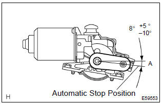
- Check that the automatic stop position is correct.
Standard: see the illustration.


Other materials:
Replacement
Hint: components:
1. Remove front wheel
2. Remove front axle hub lh nut
sst 09930–00010
3. Separate front stabilizer link assy lh
4. Separate speed sensor front lh (w/ abs)
5. Separate front disc brake caliper assy lh
Remove the 2 bolts, separate the brake caliper assy ...
Registering and connecting from the “Bluetooth* Setup” screen
To display the screen shown below, press the “SETUP” button and select “Bluetooth*”
on the “Setup” screen.
1 Select to connect the device to be used with multimedia system.
2 Select to register a Bluetooth® device to be used with multimedia system.
3 Select to set detailed Bluet ...
Circuit description
The seat position sensor circuit consists of the airbag sensor assy center
and seat position sensor.
Dtc b1153/25 is recorded when a malfunction is detected in the seat position
sensor circuit.
Wiring diagram
...