Toyota Corolla (E120) 2002–2008 Repair Manual / Diagnostics / Supplemental restraint system / Short in p squib circuit (to ground) / Inspection procedure
Toyota Corolla (E120): Inspection procedure
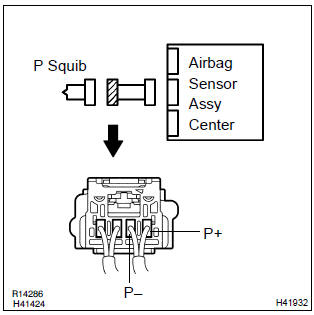
1 Check p squib circuit(airbag sensor assy center – instrument panel passenger airbag assy)
- Disconnect the negative (–) terminal cable from the battery, and wait at least for 90 seconds.
- disconnect the connectors between the airbag sensor assy center and the instrument panel passenger airbag assy.
- for the connector (on the instrument panel passenger airbag
assy side) between the airbag sensor assy center
and the instrument panel passenger airbag assy, measure
the resistance between p+ and body ground.
Ok: resistance: 1 mΩ or higher

2 Check air bag sensor assy center
Sst 09843–18040
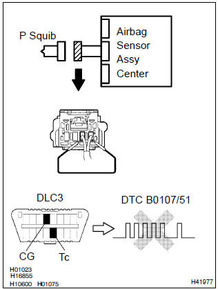
- Connect the connector to the airbag sensor assy center.
- using a service wire, connect p+ and p– of the connector (on the instrument panel passenger airbag assy side) between the airbag sensor assy center and the instrument panel passenger airbag assy.
- connect the negative (–) terminal cable to the battery, and wait at least for 2 seconds.
- turn the ignition switch to on, and wait at least for 20 seconds.
- clear the dtc stored in memory .
- turn the ignition switch to lock, and wait at least for 20 seconds.
- turn the ignition switch to on, and wait at least for 20 seconds.
- check the dtc .
Ok: dtc b0107/51 is not output.
Hint
: codes other than code b0107/51 may be output at this time, but they are not relevant to this check.


3 Check p squib
Sst 09843–18040
- Turn the ignition switch to lock.
- disconnect the negative (–) terminal cable from the battery, and wait at least for 90 seconds.
- connect the instrument panel passenger airbag assy connector.
- connect the negative (–) terminal cable to the battery, and wait at least for 2 seconds.
- turn the ignition switch to on, and wait at least for 20 seconds.
- clear the dtc stored in memory .
- turn the ignition switch to lock, and wait at least for 20 seconds.
- turn the ignition switch to on, and wait at least for 20 seconds.
- check the dtc .
Ok: dtc b0107/51 is not output.
Hint: codes other than code b0107/51 may be output at this time, but they are not relevant to this check.

4 Use simulation method to check


Replace all srs components including the wire harness


Other materials:
Inspection procedure
1 Check un–lock warning switch assy
Disconnect the key unlock warning switch connector.
check the continuity between the terminals of the key unlock
warning switch connector, as shown in the illustration
and table.
Standard:
2 Check wire harness (tvip ecu unlock warni ...
Diagnostic trouble code chart
If a dtc is displayed during the dtc check, check the circuit listed in the
table below and proceed to the
page given.
* :● ... Mil light up
...
Emergency towing
If a tow truck is not available in an emergency, your vehicle may be temporarily
towed using a cable or chain secured to the emergency towing eyelet. This should
only be attempted on hard surfaced roads for short distances at low speeds.
A driver must be in the vehicle to steer and operate the ...