Toyota Corolla (E120) 2002–2008 Repair Manual / Automatic transmission / trans / Floor shift parking lock cable assy (atm)
Toyota Corolla (E120): Floor shift parking lock cable assy (atm)
Replacement
1. Precaution
2. Disconnect battery negative terminal
3. Place front wheels facing straight ahead
4. Remove horn button assy
5. Remove steering wheel assy
sst 09950–50013 (09951–05010, 09952–05010, 09953–05020, 09954–05021)
6. Remove steering column cover
7. Remove console panel upper
8. Remove parking brake hole cover sub–assy
9. Remove console box carpet
10. Remove console box sub–assy rear
11. Remove floor shift parking lock cable assy
- Remove the cable end from the lever pin of the floor shift assembly.
- Using a screwdriver, disconnect the parking lock cable from the floor shift assembly.
- Disconnect the cable clamp.
- turn the ignition switch acc or on.
- Using a screwdriver, remove the cable from the upper bracket.
Hint
: before disconnecting the cable, keep in mind each of the physical relationship between the connector and wire harness or other cables
12. Install floor shift parking lock cable assy
- Turn the ignition switch acc or on.
- install the cable to the upper bracket.
Hint
: connect the removed cable so that it will be the same physical relationship you kept in mind before its disconnection.
- Connect the cable clamp.
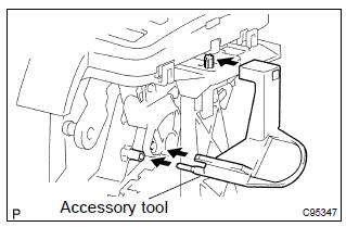
- Set the accessory tool.
- Shift the shift lever to n position and turn the ignition switch to acc or on.
- Set the accessory tool to the shift lock control unit
assy as shown in the illustration.
Accessory tool parts no.: 33693–02010
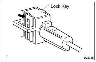
- Using a screwdriver, unlock the claw of the lock key of automatic adjustment part.
- Insert the slide cap into the through hole and install.
- Insert the lever pin into the hole in the cable end.
Hint
: fit the claws securely.
- Lock the lock key.
Hint
: at this time, the shift lever should be in n position and the ignition key should be set to acc or on.
- remove the accessory tool.
Accessory tool parts no.: 33693–02010
13. Install steering wheel assy
14. Inspect steering wheel center point
15. Install horn button assy
16. Inspect srs warning light
17. Check key interlock operation


Other materials:
Coolant
Replacement
1. Drain coolant
Caution:
to avoid the danger of being burned, do not remove the radiator
cap while the engine and radiator are still hot, as fluid
and steam can be blown out under pressure.
remove the radiator cap.
loosen the radiator and engine drain plugs, a ...
Manual air conditioning system∗
Air conditioning controls
► Heater
► Air conditioning system
■ Adjusting the temperature setting
► Heater
To adjust the temperature setting, turn the
dial clockwise to increase the temperature.
► Air conditioning system
To adjust the temperature setting, tu ...
Under hood
General maintenance
1. General notes
maintenance requirements vary depending on the country.
Check the maintenance schedule in the owner’s manual supplement.
Following the maintenance schedule is mandatory.
Determine the appropriate time to service the vehicle using either miles
driv ...