Toyota Corolla (E120) 2002–2008 Repair Manual / Front suspension / Stabilizer bar front
Toyota Corolla (E120): Stabilizer bar front
Replacement
Hint
: components:
1. Remove front wheel
2. Remove front stabilizer link assy lh
- Remove the 2 nuts and stabilizer bar link.
Hint
: if the ball joint turns together with the nut, use a hexagon wrench (6 mm) to hold the stud. 3. Remove front stabilizer link assy rh
Hint
: remove the rh side by the same procedure as the lh side.
4. Inspect front stabilizer link assy
- As shown in the illustration, flip the ball joint stud back and forth 5 times, before installing the nut.
- using a torque wrench, turn the nut continuously at a rate
of 2 – 4 seconds per 1 turn and take the torque reading
on the 5th turn.
Turning torque: 0.05 – 1.96 Nvm (0.5 – 20 Kgf·cm, 0.4 – 17 In.Vlbf)
5. Separate front suspension arm sub–assy lower no.1 Lh
6. Separate front suspension arm sub–assy lower no.1 Rh
Hint
: remove the rh side by the same procedure as the lh side.
7. Separate rack & pinion power steering gear assy
8. Suspend engine assy
at:
mt:
9. Separate front suspension crossmember sub–assy
10. Remove stabilizer bar front
- remove the 4 bolts,front stabilizer bracket no.1 Lh, front stabilizer bracket no.1 Rh, 2 front stabilizer bar bushes no.1 And stabilizer bar front from the front suspension crossmember sub–assy.
- remove the 2 front stabilizer bar bushes no.1 From the stabilizer bar front.
11. Install stabilizer bar front
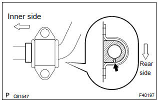
- Install 2 front stabilizer bar bushes no.1, Front stabilizer bracket no.1 Lh and front stabilizer bracket no.1 Rh to the stabilizer bar front.
Hint
: install the bushing to the inner side of the bushing stopper on the stabilizer bar.
- Install the stabilizer bar front and 4 bolts to the front suspension
crossmember sub–assy.
Torque: 19 nvm (194 Kgf·cm, 14 ft·lbf)
12. Install front suspension crossmember sub–assy sst 09670–00010
13. Install rack & pinion power steering gear assy
14. Install front suspension arm sub–assy lower no.1 Lh
15. Install front suspension arm sub–assy lower no.1 Rh
H
int
: install the rh side by the same procedures as the lh side.
16. Install front stabilizer link assy lh
- Install the stabilizer bar link with the 2 nuts.
Torque: 74 nvm (755 Kgf·cm, 55 ft·lbf)
H
int
: if the ball joint turns together with the nut, use a hexagon wrench (6 mm) to hold the stud.
17. Install front stabilizer link assy lh
Hint
: install the rh side by the same procedure as the lh side.
18. Install front wheel
torque: 103 nvm (1,050 Kgf·cm, 76 ft·lbf)
19. Inspect and adjust front wheel alignment


Other materials:
Using the voice command system (Multimedia system)
Voice command system
The voice command system enables the hands-free system to be operated using
voice commands.
Operations of the voice command system can be performed by selecting the menu
corresponding to each function on the screen. Even if any menu is selected, commands
displayed on all ...
Inspection procedure
1 Check side squib(rh) circuit(airbag sensor assy center – front
seat airbag assy rh)
Disconnect the negative (–) terminal cable from the battery,
and wait at least for 90 seconds.
disconnect the connectors between the airbag sensor
assy center and the front seat airbag assy ...
Center stop lamp assy
Replacement
1. Remove package tray trim panel assy (w/o rear spoiler)
2. Remove center stop lamp assy (w/o rear
spoiler)
Remove the center stop light assy as shown in the illustlation.
3. Remove center stop lamp assy (w/ rear
spoiler)
Remove the 2 screws.
disconnect th ...