Toyota Corolla (E120): Overhaul
1. Remove oil pump relief valve
- Remove the oil pump relief valve plug, oil pump relief valve spring and oil pump relief valve.
- Oil pump relief valve plug
- oil pump relief valve spring
- oil pump relief valve
2. Inspect oil pump assy
- Remove 3 screws and oil pump cover.
- Inspect the oil pump relief valve.
- Coat the valve with engine oil and check that it falls smoothly into the valve hole by it own weight.
- inspect the oil pump rotor sub–assembly.
- Coat the oil pump gear set with engine oil and place them into the oil pump body. Check that the rotors revolves smoothly.
- inspect rotor tip clearance.
- Using a feeler gauge, measure the clearance between
the drive and driven rotor tips.
Standard tip clearance: 0.040 – 0.160 Mm (0.0016 – 0.0063 In.)
- Inspect body clearance.
- Using a feeler gauge, measure the clearance between
the driven rotor and body.
Standard body clearance: 0.260 – 0.325 Mm (0.0102 – 0.0128 In.)
- Inspect rotor side clearance.
- Using a feeler gauge and precision straight edge,
measure the clearance between the rotors and precision
straight edge.
Standard side clearance: 0.025 – 0.071 Mm (0.0010 – 0.0028 In.)
- Install oil pump rotor sub–assembly.
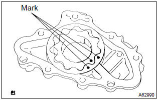
- Coat the oil pump gear set with engine oil and place it into pump body with the marks facing the pump body cover side.
- Install oil pump rotor sub–assembly.
(1) Coat the oil pump gear set with engine oil and place it into pump body with the marks facing the pump body cover side.
3. Install oil pump relief valve
- Install the oil pump relief valve plug, oil pump relief valve
spring and oil pump relief valve.
Torque: 37 nvm (375 Kgf·cm, 27 ft·lbf)
- oil pump relief valve plug
- oil pump relief valve spring
- oil pump relief valve


Other materials:
Replacement
1. Disconnect battery negative terminal
2. Remove engine under cover rh
3. Remove starter assy
Disconnect the starter connector.
open the terminal cover.
remove the nut, then disconnect the starter wire.
remove the 2 bolts, then remove the starter.
4. Install starter a ...
Basic repair hint
(A) hints on operations
1
Looks
Always wear a clean uniform.
Hat and safety shoes must be worn.
2
Vehicle protection
Set a grill cover, fender cover, seat cover and floor mat before
starting the operation.
3
Safe ...
On–vehicle inspection
1. Inspect refrigerant pressure with manifold gauge set
this is a method in witch the trouble is located by using
a manifold gauge set. Read the manifold gauge pressure
when the these conditions are established.
Test conditions:
temperature at the air inlet with the switch set
...