
Toyota Corolla (E120) 2002–2008 Repair Manual / Diagnostics / Sfi system / Idle air control System/ Circuit / Inspection procedure
Toyota Corolla (E120): Inspection procedure
Hint
:
- when the throttle position is slightly opened (the accelerator pedal is slightly depressed) because a floor carpet is overlapped on the accelerator pedal, or if not fully releasing the accelerator pedal, etc., Dtc p505 will possibly be detected.
- Read freeze frame data using the hand-held tester or the obd ii scan tool. Freeze frame data records the engine conditions when a malfunction is detected. When troubleshooting, it is useful for determining whether the vehicle was running or stopped, the engine was warmed up or not, the air–fuel ratio was lean or rich, etc. At the time of the malfunction.
Hand–held tester:
1 Check other dtc output
- Connect the hand–held tester to the dlc3.
- turn the ignition switch on and push the hand–held tester main switch on.
- read the dtcs.
Result:



2 Check connection of pcv hose


3 Check air induction system


4 Perform active test using hand–held tester(check iac valve operation)
- Warm up the engine to the normal operating temperature.
- switch off all the accessories.
- switch off the a/c.
- shift the lever into the neutral position.
- connect the hand–held tester to the dlc3.
- select the item ”diagnosis / enhanced obd ii / active test / isc duty ratio”.
- check that the engine rpm varies when changing the isc duty ratio.
Engine rpm: engine rpm fluctuates up and down in response to the isc duty ratio variation.


5 Check a/c signal circuit


6 Check blockage of iac valve and passage to bypass throttle valve


7 Check harness and connector
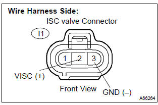
- Disconnect the i1 iac valve connector.
- turn the ignition switch on.
- measure the voltage between the terminals of the iac valve wire harness side connector.
Standard:

- Reconnect the iac valve connector.


8 Check harness and connector(iac valve – ecm)
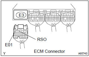
- Disconnect the i1 iac valve connector.
- disconnect the e3 ecm connector.
- check the resistance between the wire harness side connectors.
Standard (check for open):

Standard (check for short):

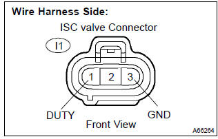
- Reconnect the ecm connector.
- reconnect the iac valve connector.


9 Inspect idle air control valve


Replace ecm
Obd ii scan tool (excluding hand–held tester):
1 Check other dtc output
- Connect the hand–held tester to the dlc3.
Result:



2 Check connection of pcv hose

3 Check air induction system

4 Check a/c signal circuit

5 Check blockage of iac valve and passage to bypass throttle valve

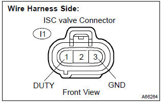
6 Check harness and connector
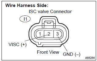
- Disconnect the i1 iac valve connector.
- turn the ignition switch on.
- measure the voltage between the terminals of the iac valve wire harness side connector.
Standard:

- Reconnect the iac valve connector.

7 Check harness and connector(iac valve – ecm)
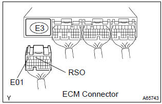
- Disconnect the i1 iac valve connector.
- disconnect the e3 ecm connector.
- check the resistance between the wire harness side connectors.
Standard (check for open):

Standard (check for short):

- Reconnect the ecm connector.
- reconnect the iac valve connector.


8 Inspect idle air control valve


Replace ecm


Other materials:
Calibrating the compass
The direction display deviates from
the true direction determined by the earth’s magnetic field. The amount of deviation
varies according to the geographic position of the vehicle.
If you cross over a map boundary shown in illustration, the compass will deviate.
To obtain higher precision or ...
Inspection procedure
1 Check connector
Disconnect the negative (–) terminal cable from the battery, and wait at
least for 90 seconds.
check the connection of the combination meter connector and the
airbag sensor assy center connectors.
Ok:
the connectors are connected.
2 Check combination ...
Circuit description
Monitor description
The ecm commands gearshift by turning the shift solenoid valves ”on/off”.
When there is an open or short
circuit in any shift solenoid valve circuit, the ecm detects the problem and the
mil comes on. Illuminating
the mil, the ecm performs the fail–safe and turns ...