Toyota Corolla (E120) 2002–2008 Repair Manual / Diagnostics / Sfi system / Idle air control System/ Circuit / Circuit description
Toyota Corolla (E120): Circuit description
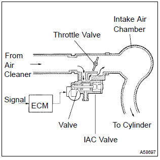
The rotary solenoid type idle air control (iac) valve is located under the throttle body and intake air bypassing the throttle valve flows into the iac valve through the passage.
In this way the intake air volume bypassing the throttle valve is regulated, controls the engine speed.
The ecm operates the iac valve only to perform idle–up and provide feedback for the target idling speed.
Monitor description
The idle speeds are determined depending on the volume of air that passes through the iac valve. When the volume is large, the idle speed becomes higher. When the volume is small, the idle speed becomes lower.
The iac valve controls the air volume that bypasses the throttle valve. The engine control module (ecm) sends duty signals to the iac valve and drives the iac valve stepper motor to determine the air volume that bypasses the throttle valve.
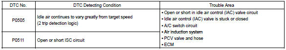
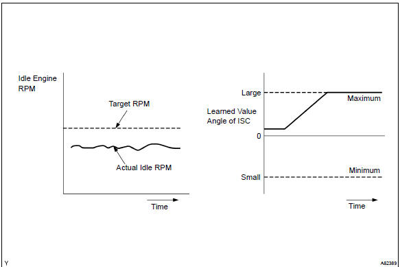
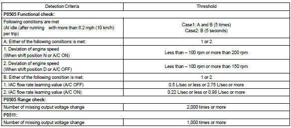
Although the ecm regulates the idle engine rpm with the feedback control in several vehicle stopped, actual idle rpm does not reach the targeted rpm and a learned valve angle of the idle air control (iac) remains at the maximum or remains at the minimum, the ecm determines to detect malfunction in the iac system.
Example: if the rpm difference between the targeted and actual idle engine rpms exceeds 200 rpm (*1) with the vehicle stopped in an idle, and this occurs 5 times, or if the learned value angle of the iac remains at its maximum or minimum angle for 5 seconds, p505 is detected.
P0511 is detected as an open/short circuit in the iac if the rate of duty signal input to the iac valve has stuck at 0 or 100 %.
*1: Threshold rpm is varied by an engine load.
Monitor strategy
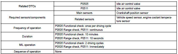
Typical enabling condition
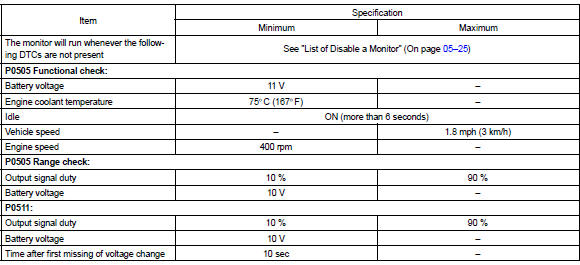
Typical malfunction thresholds
Component operating range

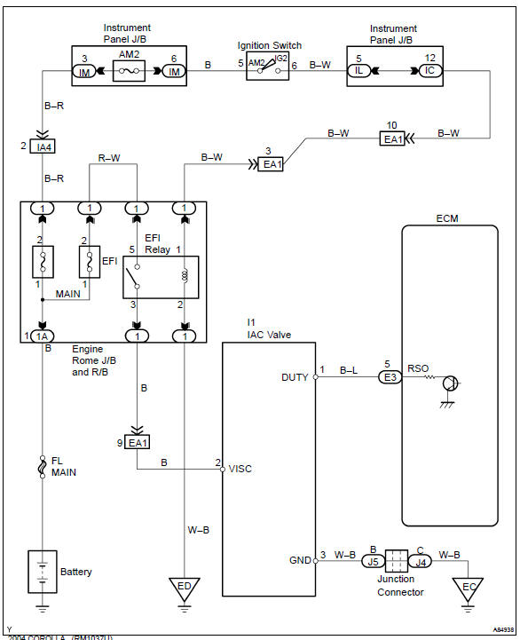
Wiring diagram


Other materials:
Seat belt warning lamp for front passenger’s seat
does not flash
Wiring diagram
Inspection procedure
1 Inspect combination meter assy
Ground terminal c9–11 on the combination meter side.
check that the warning lightlights up.
Ok: warning light lights up.
2 Inspect passenger seat belt warning lamp assy
Ground terminal c9– ...
Inspection procedure
1 Inspect parking brake switch circuit
Check for open and short circuit in parking brake switch circuit
2 Inspect brake fluid level warning switch circuit
Check the brake fluid level in reservoir.
check for open and shot circuit in brake fluid level warning
switch circuit
...
Glossary of tire terminology
*: Table 1 - Occupant loading and distribution for vehicle normal load for various
designated seating capacities
...