Toyota Corolla (E120) 2002–2008 Repair Manual / Heater & air conditioner / Air conditioning system / On–vehicle inspection
Toyota Corolla (E120): On–vehicle inspection
1. Inspect pressure switch no.1.
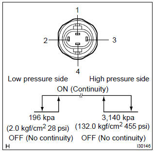
- Magnetic clutch control: inspect pressure switch operation.
- Set on the manifold gauge set.
- Connect the positive (+) lead from the ohmmeter to terminal 4 and the negative (–) lead to terminal 1.
- Check continuity between terminals when refrigerant pressure is changed, as shown in the illustration.
If operation is not as specified, replace the pressure switch.
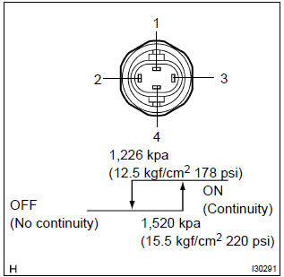
- Cooling fan control: inspect pressure switch operation.
- Connect the positive (+) lead from the ohmmeter to terminal 2 and the negative (–) lead to terminal 3.
- Check continuity between terminals when refrigerant pressure is changed, as shown in the illustration.
If operation is not as specified, replace the pressure switch.
2. Cooler compressor assy w/magnetic clutch
- connect the positive (+) lead from the battery to terminal and the negative (–) lead to the body ground.
- check that the magnetic clutch energized.
If operation is not as specified, replace the magnet clutch assy.


Other materials:
Using the radio
Radio operation
Select “AM” or “FM” to begin listening to the radio.
1 Power
2 Volume
3 Station selectors
4 Adjust frequency or select an item
5 AM/FM mode button
6 Scan for receivable stations
7 Seek a frequency
Setting station presets
1Search for a desired station by turning
...
Using the AUX port
This port can be used to connect a portable audio device and listen to it through
the vehicle’s speakers. Press until
“AUX” is displayed.
Connecting a portable player
■Operating portable audio devices connected to the audio system
The volume can be adjusted using the vehicle's ...
Replacement
Hint:
for parking brake cable assy no.2, Perform the same procedure to the parking
brake cable assy no.3.
1. Remove rear wheel
2. Remove rear brake drum sub–assy
3. Remove rear brake automatic adjust lever lh
4. Remove front brake shoe
sst 09718–00010
5. Remove parking brake sho ...