
Toyota Corolla (E120) 2002–2008 Repair Manual / Diagnostics / Combination meter / Malfunction in tachometer
Toyota Corolla (E120): Malfunction in tachometer
Wiring diagram
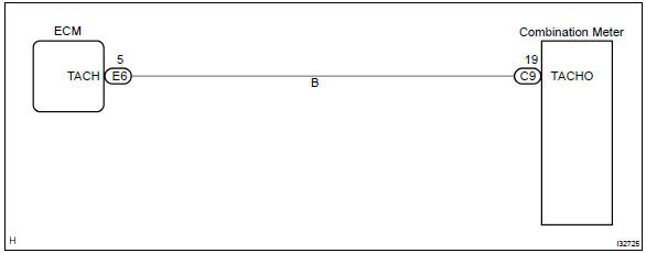
Inspection procedure

- Check output value of ecm.
- Connect the hand–held tester to dlc3.
- Turn the ignition switch to on and push the hand–held tester main switch on.
- Select the data list mode on the hand–held tester.


2 Inspect combination meter assy

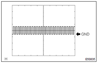
(Reference) inspection using oscilloscope
- check the input signal waveform.
- Remove the combination meter assy with connectors still connected.
- Connect the oscilloscope to the terminals c9–19 of combination meter assy and body ground.
- Start engine.
- Check the signal waveform.



3 Check harness and connector(between ecm and combination meter assy)
- Remove the combination meter.
- check the continuity between terminals 5 (tach) of ecm and c9–19 of combination meter connector.
Standard: there is continuity.


Check and replace ecm


Other materials:
SRS airbags
The SRS airbags inflate when the vehicle is subjected to certain types of
severe impacts that may cause significant injury to the occupants. They work together
with the seat belts to help reduce the risk of death or serious injury.
◆ SRS front airbags
1 SRS driver airbag/front passenge ...
Out side moulding
Replacement
Hint:
use the same procedures for the rh side and lh side.
1. Remove outside moulding
Put protective tape around the moulding.
insert a piano wire between the vehicle body and moulding.
tie objects that can serve as handles (for example, wooden
blocks) to all ...
Child restraint system
fixed with a seat belt
A child restraint system for a
small child or baby must itself be
properly restrained on the seat
with the lap portion of the
lap/shoulder belt.
■ Installing child restraint
system using a seat belt
(child restraint lock function
belt)
Install the child restraint system
in accordance to the operat ...