Toyota Corolla (E120) 2002–2008 Repair Manual / Diagnostics / Combination meter / Malfunction in speedometer
Toyota Corolla (E120): Malfunction in speedometer
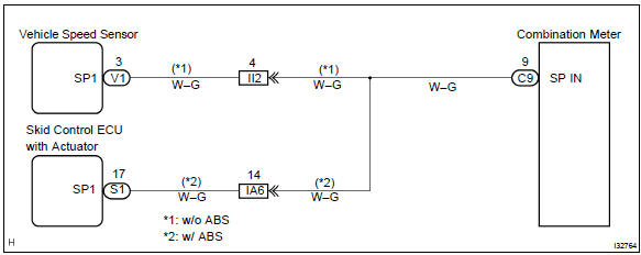
Wiring diagram
Inspection procedure
1 Check combination meter assy
- Remove the combination meter assy with connector still connected.
- check voltage.
- Jack up either of the front wheels.
- Shift the shift lever to neutral.
- Turn the ignition switch to on.
- Measure the voltage between terminals c9–9 of combination meter assy and body ground when front wheel is turning slowly.
Standard voltage: voltage is generated intermittently.
Result:


Check and replace combination meter assy
2 Check obd ii scan tool or hand–held tester
- Check output value of skid control ecu.
- Connect the hand–held tester to dlc3.
- Turn the ignition switch to on and push the hand–held tester main switch on.
- Select the data list mode on the hand–held tester.
- Check that there is no difference between the speed value output
from the speed sensor displayed
by the hand–held tester and the speed value displayed by the speedometer
when driving
the vehicle.
Ok: there is almost no difference from the displayed speed value.


Repair or replace harness or connector
3 Inspect speedometer sensor
- Check voltage.
- Shift the shift lever to neutral.
- Jack up either of the front wheel.
- Turn the ignition switch to on.
- Measure voltage between terminals 3 and 2 of speed sensor when the front wheel is turning slowly.
Standard voltage: voltage is generated intermittently.

Repair or replace harness or connector


Other materials:
Replacement
1. Disconnect battery negative terminal
2. Remove engine under cover rh
3. Remove starter assy
Disconnect the starter connector.
open the terminal cover.
remove the nut, then disconnect the starter wire.
remove the 2 bolts, then remove the starter.
4. Install starter a ...
Inspection procedure
1 Check p/t squib(rh) circuit(airbag sensor assy center – front
seat outer belt assy rh)
Disconnect the negative (–) terminal cable from the battery,
and wait at least for 90 seconds.
disconnect the connectors between the airbag sensor
assy center and the seat belt pretensio ...
How to proceed with troubleshooting
Hint:
carry out troubleshooting in accordance with the procedures on the following
page. Here, only the basic
procedures are shown. Details are provided in the diagnostics section, showing
the most effective methods
for each circuit. Confirm the troubleshooting procedures first for the releva ...