Toyota Corolla (E120): Inspection procedure
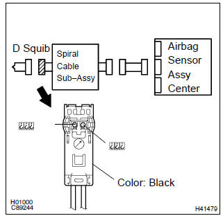
1 Check d squib circuit(airbag sensor assy center – horn button assy)
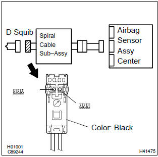
- Disconnect the negative (–) terminal cable from the battery, and wait at least for 90 seconds.
- disconnect the connector between the airbag sensor assy center and the horn button assy.
- for the black connector (on the spiral cable sub–assy
side) between the horn button assy and the spiral cable
sub–assy, measure the resistance between d2+ and
body ground.
Ok: resistance: 1 mw or higher


2 Check air bag sensor assy center
Sst 09843–18040
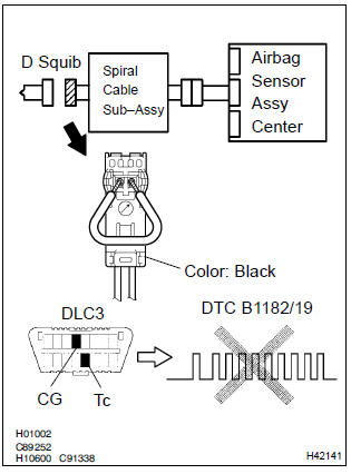
- Connect the connector to the airbag sensor assy center.
- using a service wire, connect d2+ and d2– of the black connector (on the spiral cable sub–assy side) between the horn button assy and the spiral cable sub–assy.
- connect the negative (–) terminal cable to the battery, and wait at least for 2 seconds.
- turn the ignition switch to on, and wait t least for 20 seconds.
- clear the dtc stored in memory .
- turn the ignition switch to lock, and wait at least for 20 seconds.
- turn the ignition switch to on, and wait at least for 20 seconds.
- check the dtc .
Ok: dtc b1182/19 is not output.
Hint
: codes other than code b1182/19 may be output at this time, but they are not relevant to this check.


3 Check d squib
Sst 09843–18040
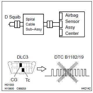
- Turn the ignition switch to lock.
- disconnect the negative (–) terminal cable from the battery, and wait at least for 90 seconds.
- connect the horn button assy connectors.
- connect the negative (–) terminal cable to the battery, and wait at least for 2 seconds.
- turn the ignition switch to on, and wait at least for 20 seconds.
- clear the dtc stored in memory .
- turn the ignition switch to lock, and wait at least for 20 seconds.
- turn the ignition switch to on, and wait at least for 20 seconds.
- check the dtc .
Ok: dtc b1182/19 is not output.
Hint
: codes other than code b1182/19 may be output at this time, but they are not relevant to this check.


4 Use simulation method to check


Replace all srs components including the wire harness
5 Check instrument panel wire(airbag sensor assy center – spiral cable sub–assy)
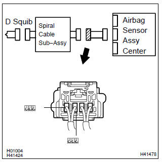
- Disconnect the connector of the instrument panel wire.
- for the connector (on the spiral cable sub–assy side) between
the airbag sensor assy center and the spiral cable
sub–assy, measure the resistance between d2+ and
body ground.
Ok: resistance: 1 mΩ or higher

6 Check spiral cable sub–assy
- For the black connector (on the spiral cable sub–assy
side) between the horn button assy and the spiral cable
sub–assy, measure the resistance between d2+ and
body ground.
Ok: resistance: 1 mΩ or higher


7 Use simulation method to check

Replace all srs components including the wire harness


Other materials:
Changing gears in the M
position
To enter 10-speed sport
sequential shiftmatic mode, shift
the shift lever to M position.
Gear steps can then be selected
by operating the shift lever or
paddle shift switches, allowing
you to drive in the gear step of
your choosing.
Upshifting
Downshifting
The gear changes once every time
the ...
Sound setting
1 Display the “Phone/Message Settings” screen. 2 Select “Sound Settings” on the
“Phone/Message Settings” screen.
1 Set the desired ringtone.
2 Adjust the ringtone volume.
3 Adjust the message readout volume.
4 Set the desired incoming SMS/MMS tone.
5 Adjust the incoming SMS/ MMS t ...
Eco Driving Indicator Light customization (except vehicles with a manual transmission)
Eco Driving Indicator Light can be activated or deactivated.
1 While the odometer is being displayed, press and hold the “DISP” switch to
display the Eco Driving Indicator Light customization screen.
2 Press the “DISP” switch to set Eco Driving Indicator Light to on or off.
3 Press and ...