Toyota Corolla (E120) 2002–2008 Repair Manual / Diagnostics / Toyota vehicle intrusion protection system / Ignition switch circuit / Inspection procedure
Toyota Corolla (E120): Inspection procedure
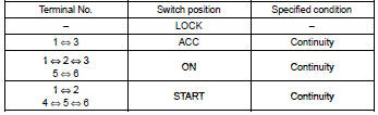
1 Check ignition or starter switch assy
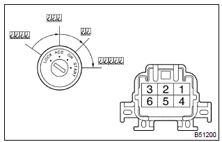
- Check the ignition switch, as shown in the illustration and table.
Standard:

2 Check fuse (ecu–b)
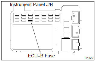
- Remove the fuse from the instrument panel j/b.
- check the continuity of the fuse.
Standard: continuity


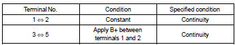
3 Check relay (marking: ig1)
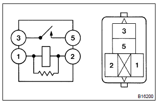
- Remove the relay from the instrument j/b.
- inspect the relay continuity, as shown in the illustration and table.
Standard:


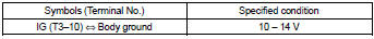
4 Check tvip ecu
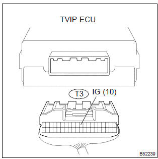
- Disconnect the tvip ecu connector.
- turn the ignition switch on.
- measure the voltage between the terminal of the ecu connector and the body ground, as shown in the illustration and table.
Standard:

Check and replace tvip ecu


Other materials:
Supplemental restraint system
Preparation
Sst
Recomended tools
Equipment
...
Circuit description
The seat position sensor circuit consists of the airbag sensor assy center
and seat position sensor.
Dtc b1153/25 is recorded when a malfunction is detected in the seat position
sensor circuit.
Wiring diagram
...
Inspection procedure
1 Inspect dlc3 terminal voltage(tc terminal)
Turn the ignition switch to on.
measure voltage between terminals tc and cg of dlc3.
Ok:
voltage: 10 – 14 v
2 Check harness and connector(dlc3 – body ground)
Check for open and short circuit in harness and connector betw ...