Toyota Corolla (E120) 2002–2008 Repair Manual / Diagnostics / Supplemental restraint system / Airbag sensor assy malfunction / Inspection procedure
Toyota Corolla (E120): Inspection procedure
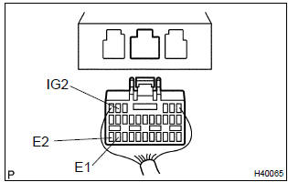
1 Check voltage at ig2 of airbag sensor assy center
- Disconnect the negative (–) terminal cable from the battery, and wait at least for 90 seconds.
- disconnect the connector of the airbag sensor assy center.
- connect the negative (–) terminal cable to the battery, and wait at least for 2 seconds.
- turn the ignition switch to on.
- measure the voltage between e1 (e2) and ig2 of the airbag
sensor assy center connector.
Ok: voltage: 10 – 14 v

2 Check air bag sensor assy center
Sst 09843–18040
- Turn the ignition switch to lock.
- disconnect the negative (–) terminal cable from the battery, and wait at least for 90 seconds.
- connect the connectors of all the srs components.
- connect the negative (–) terminal cable to the battery, and wait at least for 2 seconds.
- turn the ignition switch to on, and wait at least for 20 seconds.
- clear the dtc stored in memory .
- turn the ignition switch to lock, and wait at least for 20 seconds.
- turn the ignition switch to on, and wait at least for 20 seconds.
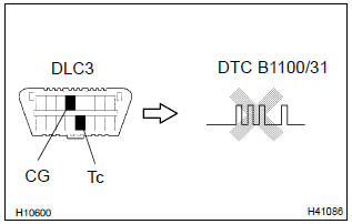
- check the dtc .
Ok: dtc b1100/31 is not output.
Hint
: codes other than code b1100/31 may be output at this time, but they are not relevant to this check.


Use simulation method to check


Other materials:
Precaution
1. Work precautions
(A) vehicle protection
(1) when welding, cover glass, seats, carpets, etc. With
heat resistant fireploof covers to protect them.
(B) safety
(1) never stand in the path of the chain when using a puller
on the body or frame, and be sure to attach a safety
cable.
...
Center stop lamp assy
Replacement
1. Remove package tray trim panel assy (w/o rear spoiler)
2. Remove center stop lamp assy (w/o rear
spoiler)
Remove the center stop light assy as shown in the illustlation.
3. Remove center stop lamp assy (w/ rear
spoiler)
Remove the 2 screws.
disconnect th ...
Inspection procedure
1 Check side air bag sensor assy rh
Sst 09843–18040
Connect the negative (–) terminal cable to the battery,
and wait at least for 2 seconds.
turn the ignition switch to on, and wait at least for 20 seconds.
clear the dtc stored in memory .
turn the ignition swi ...