Toyota Corolla (E120) 2002–2008 Repair Manual / Diagnostics / Supplemental restraint system / Seat belt buckle switch (lh)
malfunction / Inspection procedure
Toyota Corolla (E120): Inspection procedure
1 Check wire harness(airbag sensor assy center – front seat inner belt assy lh)
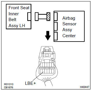
- Disconnect the negative (–) terminal cable from the battery, and wait at least for 90 seconds.
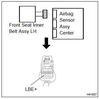
- disconnect the connectors between the airbag sensor assy center and the front seat inner belt assy (lh).
- for the connector (on the airbag sensor assy center side)
between the airbag sensor assy center and the front seat
inner belt assy (lh), measure the resistance between
lbe+ and body ground.
Ok: resistance: 1 mw or higher

2 Check wire harness(airbag sensor assy center – front seat inner belt assy lh)
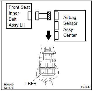
- Connect the negative (–) terminal cable to the battery, and wait at least for 2 seconds.
- turn the ignition switch to on.
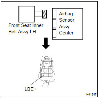
- for the connector (on the airbag sensor assy center side)
between the airbag sensor assy center and the front seat
inner belt assy (lh), measure the voltage between lbe+
and body ground.
Ok: voltage: below 1 v

3 Check front seat inner belt assy lh
- Turn the ignition switch to lock.
- disconnect the negative (–) terminal cable from the battery, and wait at least for 90 seconds.
- connect the connector of the front seat inner belt assy (lh).
- unlock the seat belt for the front driver’s seat.
- for the connector (on the airbag sensor assy center side),
measure the resistance between lbe+ and body ground.
Ok: resistance: 1.0 Kw – 1.6 KΩ


4 Check front seat inner belt assy lh
- Lock the seat belt for the front driver’s seat.
- for the connector (on the airbag sensor assy center side),
measure the resistance between lbe+ and body ground.
Ok: resistance: 100 w – 500 Ω


5 Check air bag sensor assy center
Sst 09843–18040
- Connect the connector to the airbag sensor assy center.
- connect the negative (–) terminal cable to the battery, and wait at least for 2 seconds.
- turn the ignition switch to on, and wait at least for 20 seconds.
- clear the dtc stored in memory .
- turn the ignition switch to lock, and wait at least for 20 seconds.
- turn the ignition switch to on, and wait at least for 20 seconds.
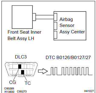
- check the dtc .
Ok: dtc b0126/b0127/27 is not output.
Hint
: codes other than code b0126/b0127/27 may be output at this time, but they are not relevant to this check.


Use simulation method to check


Other materials:
Do-it-yourself service precautions
If you perform maintenance by yourself, be sure to follow the correct procedure
as given in these sections.
CAUTION
The engine compartment contains many mechanisms and fluids that may move suddenly,
become hot, or become electrically energized. To avoid death or serious injury,
observe t ...
Cigarette lighter assy
Replacement
Hint: components:
1. Remove floor shift shift lever knob sub–assy (m/t transaxle)
2. Remove console panel upper
3. Remove cigarette lighter cover
Disengage the 2 claws and remove the cigarette lighter
cover.
4. Remove cigarette lighter assy
Turn the socket in ...
Circuit description
The vapor pressure sensor, vsv for canister closed valve (ccv), vsv for
pressure switching valve are used
to detect abnormalities in the evaporative emission control system.
The ecm decides whether there is an abnormality in the evaporative emission
control system based on the
vapor pressur ...