Toyota Corolla (E120) 2002–2008 Repair Manual / Diagnostics / Supplemental restraint system / Open in d squib circuit / Inspection procedure
Toyota Corolla (E120): Inspection procedure
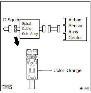
1 Check d squib circuit(airbag sensor assy center – horn button assy)
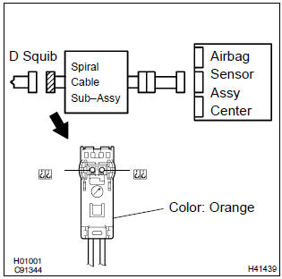
- Disconnect the negative (–) terminal cable from the battery, and wait at least for 90 seconds.
- disconnect the connectors between the horn button assy and the airbag sensor assy center.
- for the orange connector (on the spiral cable sub–assy
side) between the horn button assy and the spiral cable
sub–assy, measure the resistance between d+ and d–.
Ok: resistance: below 1 Ω


2 Check air bag sensor assy center
Sst 09843–18040
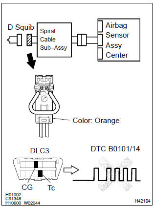
- Connect the connector to the airbag sensor assy center.
- using a service wire, connect d+ and d– of the orange connector (on the spiral cable sub–assy side) between the horn button assy and the spiral cable sub–assy.
- connect the negative (–) terminal cable to the battery, and wait at least for 2 seconds.
- turn the ignition switch to on, and wait at least for 20 seconds.
- clear the dtc stored in memory .
- turn the ignition switch to lock, and wait at least for 20 seconds.
- turn the ignition switch to on, and wait at least for 20 seconds.
- check the dtc .
Ok: dtc b0101/14 is not output.
Hint
: codes other than code b0101/14 may be output at this time, but they are not relevant to this check.


3 Check d squib
Sst 09843–18040
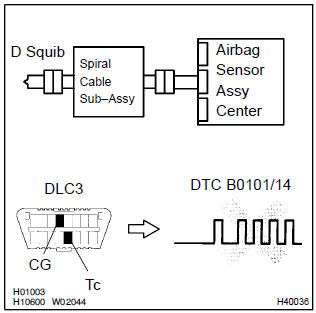
- Turn the ignition switch to lock.
- disconnect the negative (–) terminal cable from the battery, and wait at least for 90 seconds.
- connect the horn button assy connector.
- connect the negative (–) terminal cable to the battery, and wait at least for 2 seconds.
- turn the ignition switch to on, and wait at least for 20 seconds.
- clear the dtc stored in memory .
- turn the ignition switch to lock, and wait at least for 20 seconds.
- turn the ignition switch to on, and wait at least for 20 seconds.
- check the dtc .
Ok: dtc b0101/14 is not output.
Hint
: codes other than code b0101/14 may be output at this time, but they are not relevant to this check.


Use simulation method to c
4 Check instrument panel wire(airbag sensor assy center – spiral cable sub–assy)
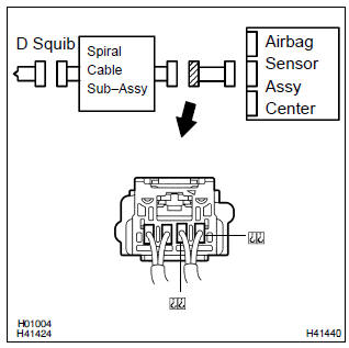
- Disconnect the connector of the instrument panel wire.
- for the connector (on the spiral cable sub–assy side) between
the airbag sensor assy center and the spiral cable
sub–assy, measure the resistance between d+ and d–.
Ok: resistance: below 1 Ω

5 Check spiral cable sub–assy
- For the orange connector (on the spiral cable sub–assy
side) between the horn button assy and the spiral cable
sub–assy, measure the resistance between d+ and d–.
Ok: resistance: below 1 Ω


Use simulation method to check


Other materials:
Combination meter assy
Overhaul
Hint: components:
1. Remove meter hood sub–assy
2. Remove combination meter assy
Remove the screw.
disengage the 2 clips as shown in the illustration.
disconnect the connector, then remove the combination
meter.
3. Remove combination meter glass
Di ...
Inspection procedure
Hint:
if dtcs p0115, p0116, p0117, p0118 and p0125 are output
simultaneously, the engine coolant temperature
sensor circuit may be open or short. Perform the troubleshooting of dtc
p0115, p0117 or
p0118 first.
Read freeze frame data using the hand-held tester or the obd ii scan
to ...
Check dlc3
The vehicle’s ecm uses the iso 9141–2 for communication
protocol. The terminal arrangement of the dlc3 complies
with sae j1962 and matches the iso 9141–2 format.
Hint:
if the display shows unable to connect to vehicle
when you have connected the cable of the obd ii scan tool or
the h ...