Toyota Corolla (E120): Inspection procedure
1 Inspect fuse(ecu–ig fuse)
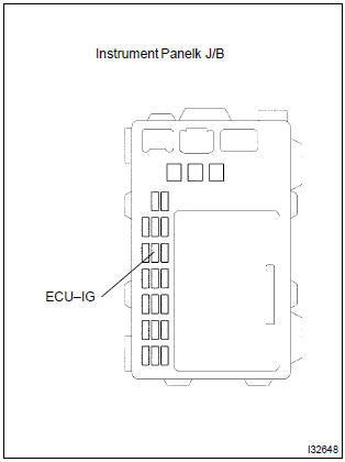
- Remove ecu–ig fuse from the instrument panel j/b.
- check continuity of ecu–ig fuse.
Ok: continuity

2 Inspect battery
Ok: voltage: 10 – 14 v


3 Inspect skid control ecu connector(ig1 terminal voltage)
In case of using hand–held tester:
- check the voltage condition output from the ecu displayed on the
hand–held tester.
Ok: ”normal” is displayed.
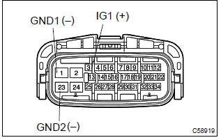
In case of not using hand–held tester:
- disconnect the skid control ecu connector.
- turn the ignition switch to on.
- measure voltage between terminals ig1 (3) and gnd (1,
23) of skid control ecu harness side connector.
Ok: oltage: 10 – 14 v


4 Inspect skid control ecu connector(gnd terminal continuity)
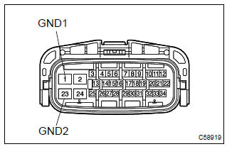
Measure resistance between terminal gnd (1, 23) of skid control ecu harness side connector and body ground.
Ok: resistance: 1 Ω or less

Check and replace brake actuator assy


Other materials:
Overhaul
Notice: when installing, coat the parts indicated by the arrow with
power steering fluid or molybdenum disulfide lithium base grease.
1. Precaution
2. Disconnect battery negative terminal
3. Inspect center front wheel
4. Remove horn button assy
5. Remove steering wheel assy
sst 09950–50013 ...
Inspection procedure
Hint:
read freeze frame data using the hand-held tester or the obd ii scan tool.
Freeze frame data records the
engine conditions when a malfunction is detected. When troubleshooting, it is
useful for determining whether
the vehicle was running or stopped, the engine was warmed up or not, the ...
Using the rear view monitor system
■ Screen description
1 Vehicle width guide lines
The line indicates a guide path when the vehicle is being backed straight up.
The displayed width is wider than the actual vehicle width.
2 Vehicle center guide lines
These lines indicate the estimated vehicle center on the ground.
3 Dis ...