Toyota Corolla (E120) 2002–2008 Repair Manual / Diagnostics / ABS with EBD system / Right/Left front speed sensor circuit / Inspection procedure
Toyota Corolla (E120): Inspection procedure
Hint
: start the inspection from step 1 in case of using the hand–held tester and start from step 2 in case of not using the hand–held tester.
1 Read value of hand–held tester(front speed sensor)
- Select the datalist mode on the hand–held tester.
- check that there is no difference between the speed value output
from the speed sensor displayed
by the hand–held tester and the speed value displayed by the speedometer
when driving the vehicle.
Ok: there is almost no difference in the displayed speed value.
Hint
: there is tolerance of 10 % in the speedometer indication.


2 Inspect front speed sensor
- Remove the fender liner.
- disconnect the speed sensor connector.
- measure resistance between terminals 1 and 2 of the
speed sensor connector.
Ok: 0.6 – 2.5 Kw or 0.9 – 1.8 Kw at 20 c
- measure resistance between each of terminals 1 and 2 of
speed sensor connector and body ground.
Ok: resistance: 1 mw or higher
Notice
: check the speed sensor signal last

3 Check harness and connector(front speed sensor – skid control ecu)
- Check for open and short circuit in harness and connector between each front speed sensor and skid control ecu

4 Inspect speed sensor and sensor rotor serrations
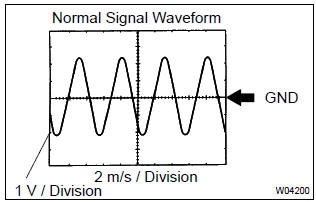
(Reference) inspection using oscilloscope
- connect the oscilloscope to the terminal fr+ – fr– and fl+ – fl– of the skid control ecu.
- drive the vehicle at about 30 km/h (19 mph), and check the signal waveform.
Hint
:
- as the vehicle speed (wheel revolution speed) increases, a cycle of the waveform becomes shorter and the fluctuation in the output voltage becomes greater.
- When noise is identified in the waveform on the oscilloscope, error signals are generated due to the speed sensor rotor’s scratches, looseness or foreign matter deposited on it.

5 Inspect front speed sensor installation
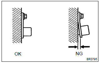
- Check the speed sensor installation.
Ok: the installation bolt is tightened properly and there is no clearance between the sensor and front steering knuckle.
Torque: 8.0 Nvm (82 kgf·cm, 71 in.Vlbf)
Notice
: check the speed sensor signal last

6 Inspect speed sensor tip
- Remove the front speed sensor .
- check the sensor tip.
Ok: no scratches or foreign objects on the sensor tip.

Notice
: check the speed sensor signal last

7 Inspect speed sensor rotor
- Remove the front speed sensor rotor .
- check the sensor rotor serrations.
Ok: no scratches, missing teeth or foreign objects.
Hint
: if foreign matter is attached, remove it and after reassembling, check the output waveform.

Notice
: check the speed sensor signal last
Check and replace brake actuator assy


Other materials:
Menu list of the Bluetooth® audio/phone
To enter a menu, press and navigate
menus by using :
*: Bluetooth is a registered trademark of Bluetooth SIG, Inc.
■Bluetooth® audio/phone system functions
Depending on the Bluetooth® device, certain functions may not be available. ...
Cleaning and protecting the vehicle interior
The following procedures will help protect your vehicle’s interior and keep
it in top condition:
Protecting the vehicle interior
Remove dirt and dust using a vacuum cleaner. Wipe dirty surfaces with a cloth
dampened with lukewarm water.
Cleaning the synthetic leather areas
● Remove l ...
Unlocking and locking the doors from the outside
◆ Smart key system (if equipped)
Carry the electronic key to enable this function.
1 Grip the driver’s door handle to unlock the door. Grip the passenger’s door
handle to unlock all the doors.* Make sure to touch the sensor on the back of the
handle.
The doors cannot be unlocked for ...