Toyota Corolla (E120) 2002–2008 Repair Manual / Diagnostics / Sfi system / Crankshaft position sensor ”a”
circuit / Inspection procedure
Toyota Corolla (E120): Inspection procedure
Hint
:
- perform the troubleshooting of dtc p0335 first. If no trouble is
found, troubleshoot the engine mechanical
systems.
Read freeze frame data using the hand-held tester or the obd ii scan tool. Freeze frame data records the engine conditions when a malfunction is detected. When troubleshooting, it is useful for determining whether the vehicle was running or stopped, the engine was warmed up or not, the air–fuel ratio was lean or rich, etc. At the time of the malfunction.
- Read value of hand–held tester or obd ii scan tool
(a) connect the hand–held tester or the obd ii scan tool to the dlc3.
(B) start the engine and push the hand–held tester or the obd ii scan tool main switch on.
(C) select the item ”diagnosis / enhanced obd ii / data list / all / engine spd”.
- The engine speed can be confirmed in data list using the hand–held tester or obd ii scan tool. If there is no ne signals from the crankshaft position sensor despite the engine revolving, the engine speed will be indicated as zero. If voltage output of the crankshaft position sensor is insufficient, the engine speed will be indicated as lower prm (than the actual rpm).
1 Inspect crankshaft position sensor(resistance)
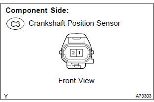
- Disconnect the c43crankshaft position sensor connector.
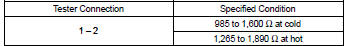
- measure the resistance between the terminals of the crankshaft position sensor connector.
Standaed:
Notice
: ”cold” and ”hot” shown above mean the temperature of the coils themselves. ”Cold” is from –10 c (14 f) to 50 c (122 f) and ”hot” is from 50 c (122 f) to 100 c (212 f).
- reconnect the crankshaft position sensor connector.

2 Check harness and connector(crankshaft position sensor – ecm)
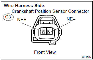
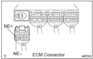
- Disconnect the c3 crankshaft position sensor connector.
- disconnect the e3 ecm connector.
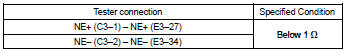
- check the resistance between the wire harness side connectors.
Standard (check for open):
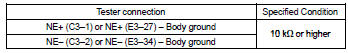
Standard (check for short):
- Reconnect the ecm connector.
- reconnect the crankshaft position sensor connector.

3 Check sensor installation(crankshaft position sensor)
- Check the crankshaft position sensor installation .


4 Check crankshaft position sensor plate(teeth of sensor plate(crankshaft))
- Check the teeth of the sensor plate.

Replace ecm


Other materials:
Replacement
Hint:
installation is in the reverse order of the removal. But the installation is
indicated only when it has a point.
1. Remove rear door opening trim rh
2. Remove rear door opening trim lh
3. Remove rear seat cushion assembly ( or 72–8)
4. Remove rear seat back assy (fixed type rear seat) ...
Seat belts
Make sure that all occupants
are wearing their seat
belts before driving the
vehicle.
WARNING
Observe the following precautions
to reduce the risk of injury in the
event of sudden braking, sudden
swerving or an accident.
Failure to do so may cause death
or serious injury.
■Wearing a seat belt
E ...
Replacement
Hint:
installation is in the reverse order of the removal. But the installation is
indicated only when it has a point.
1. Remove luggage compartment door cover
2. Remove rear spoiler
remove the 2 screws.
disconnect the wire harness connector.
put protective tape.
&nb ...