Toyota Corolla (E120): Overhaul
1. Remove console panel upper
2. Remove console box carpet
3. Remove parking brake hole cover sub–assy
4. Remove console box sub–assy rear
5. Disconnect floor shift cable transmission control shift
- Remove the cable end from the rod of the floor shift assembly.

- Using a screw driver, disconnect the control cable from the shift lever plate.
6. Disconnect floor shift parking lock cable assy
- Remove the cable end from the lever pin of the floor shift assembly.
- Using a screw driver, disconnect the parking lock cable from the floor shift assembly.
7. Remove floor shift assy
- disconnect the 2 connector.
- Disconnect the 2 wire harness clamps from the shift lever assy.
- remove the 4 bolts and floor shift assy.
8. Remove floor shift shift lever knob sub–assy
- Releasing the lock by pressing the slick, disconnect the indicator lamp wire connector from the shift lever plate.
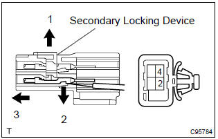
- Disengage the secondary locking device.
- using a small screwdriver, disengage the locking lug of the terminals 2 and 4, and pull the terminals out from the rear.
- disconnect the wire harness from the clamps.
- Remove the 2 screws and shift lever knob sub–assembly.
Notice
: pay attention not to apply unnatural load to transmission control switch wire harness.
9. Remove floor shift shift lever knob cover
- Remove the shift lever knob cover.
10. Remove transmission control switch
- Using a small screw driver, remove the transmission control switch.
11. Remove shift lever knob button
- Remove the shift lever knob button and spring.
12. Remove indicator lamp wire sub–assy
- Remove the indicator lamp wire sub–assy.
- remove the cap and bulb from the indicator lamp wire sub–assy.
13. Remove shift lock release button cover
- Using a screwdriver, remove the shift lock release button cover.
14. Remove position indicator housing upper

- Using a screwdriver, release the 4 claws and remove the position indicator housing upper.
15. Remove control position indicator plate
- Remove the position indicator plate from the position indicator housing upper.
16. Remove position indicator slide cover
- Remove the position indicator slide cover.
17. Remove position indicator housing lower
- Using a screwdriver, release the 3 claws and remove the position indicator housing lower.
18. Remove shift lock release button
- Remove the shift lock release button and spring.
19. Remove shift lock control unit assy
- Using a screwdriver, remove the toggle lever support pin and shift lock control unit assy.
Notice
: work so as not to damage the stopper position.
20. Remove shift lever insert no.1
21. Install shift lever insert no.1
22. Install shift lock control unit assy
- Install the shift lock control unit assy and toggle lever support pin.
Notice
: work so as not to damage the stopper position.
23. Install shift lock release button
- Apply mp grease on the shift lock release spring and shift lock release button.
- install the shift lock release button and shift lock release spring to the position indicator housing lower.
Hint
: fit the claws securely.
24. Install position indicator housing lower
- Install the position indicator housing lower.
Hint
: fit the claws securely.
25. Install position indicator slide cover
- Install the position indicator slide cover.
26. Install control position indicator plate
- Install the position indicator plate to the position indicator housing upper.
27. Install position indicator housing upper

- Install the position indicator housing upper.
Hint
: fit the claws securely.
28. Install shift lock release button cover
- Install the shift lock release button cover to the position indicator housing upper.
29. Install indicator lamp wire sub–assy
- Install the bulb and cap to the indicator lamp wire sub– assy.
- install the indicator lamp wire sub–assy.
30. Install shift lever knob button
- Apply mp grease to the spring and shift lever knob button.
- install the spring and shift lever knob button.
Hint
: fit the claws securely
31. Install transmission control switch
- Insert the wire harness into the shift lever knob from the part shown by the arrow, and install the transmission control switch to the shift lever knob.
Hint
: fit the claws securely.
32. Install floor shift shift lever knob cover
- Install the shift lever knob cover.
33. Install floor shift shift lever knob sub–assy
- Install the shift lever knob sub–assembly with the 2 screws.
Hint
: coat the threads of screws with sealant. Sealant: part no. 08833–00080, Three bond 1344, loctite 242 or equivalent N
otice
: make sure not to catch wire harness.
- Install the 2 terminals into the indicator lamp wire connector.
- Install the wire harness and connector as shown in the illustration.
34. Install floor shift assy
- Install the floor shift assy with the 4 bolts.
Torque: 12 nvm (122 Kgf·cm, 9 ft·lbf) H
int
: tighten them in the order, a, b, c and d.
- connect the 2 wire harness clamps to the shift lever plate.
- connect the 2 connector.
35. Connect floor shift cable transmission control shift
- Install the control cable to the shift lever plate.
Hint
: fit the claws securely.
- Install the cable end to the rod of the floor shift assy.
Hint
: install it with the uneven surface facing upward.
36. Connect floor shift parking lock cable assy
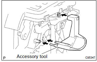
- Set the accessory tool.
- Shift the shift lever to n position and turn the ignition switch to acc or on.
- Set the accessory tool to the shift lock control unit
assy as shown in the illustration.
Accessory tool parts no.: 33693–02010
Hint
: only in the case of reusing the shift lock control unit assy.
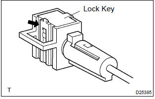
- using a screwdriver, unlock the claw of the lock key of automatic adjustment parts.
- Insert the slide cap into the through hole and install.
Hint
: fit the claws securely.
- Insert the lever pin into the hole in the cable end.
Hint
: fit the claws securely.
- Lock the lock key.
Hint
: at this time, the shift lever should be in n position and the ignition key should be set to acc or on.
- remove the accessory tool.
Accessory tool parts no.: 33693–02010
37. Check key interlock operation
38. Check shift lock operation
39. Check shift lock release button operation


Other materials:
Follow the correction procedures. (vehicles with a smart key system and with
a drive monitor display)
After taking the specified steps to correct the suspected problem, check that
the warning light turns off.
■SRS warning light
This warning light system monitors the airbag sensor assembly, front impact
sensors, side impact sensors (front door), side impact sensors (front), side impac ...
Automatic transaxle assy (atm)
Precaution
The automatic transaxle is composed of highly precision–finished
parts, necessitating careful
inspection before reassembly because even a small nick could cause fluid
leakage or affect
the performance. The instructions here are organized so that you work on
only o ...
Inspection procedure
1 Check p squib circuit(airbag sensor assy center – instrument
panel passenger airbag assy)
Disconnect the negative (–) terminal cable from the battery,
and wait at least for 90 seconds.
disconnect the connectors between the airbag sensor
assy center and the instrument panel ...