
Toyota Corolla (E120) 2002–2008 Repair Manual / Diagnostics / Toyota vehicle intrusion protection system / How to proceed with troubleshooting
Toyota Corolla (E120): How to proceed with troubleshooting
Troubleshoot in accordance with the procedure on the following pages.
1 Vehicle brought to workshop

2 Customer problem analysis check and symptom check
- Without applicable symptoms, proceed to ”a”.
- with applicable symptoms, proceed to ”b”.


3 Symptom simulation

4 Problem symptoms table
- Without applicable symptoms, proceed to ”a”.
- with applicable symptoms, proceed to ”b”.


5 Circuit inspection and part inspection

6 Perform troubleshooting in the following method, depending on malfunction symptom
- Terminals of ecu (seepage 05–703)
- on–vehicle inspection
7 Adjustment, repair or replacement

8 Confirmation test

End
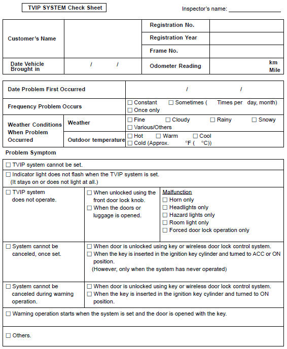
Customer problem analysis check
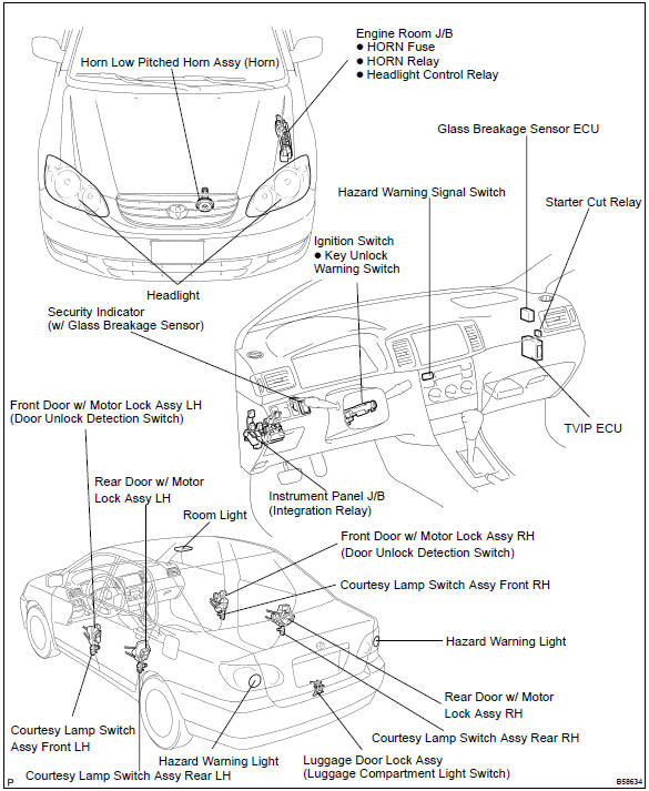
Location


Other materials:
Emergency flashers
The emergency flashers are used to warn other drivers when the vehicle has
to be stopped in the road due to a breakdown, etc.
Press the switch.
All the turn signal lights will flash.
To turn them off, press the switch once again.
■Emergency flashers
If the emergency flashers are used ...
Replacement
1. Discharge refrigerant from refrigeration system
turn the a/c switch on.
operating the cooler compressor at the engine rpm of approx. 1000
For 5 to 6 min., Circulate the refrigerant
and collect compressor oil remaining in each component into the cooler
compressor as much ...
Inspection and adjustment procedure
1 Tire valve
2 Tire pressure gauge
1 Remove the tire valve cap.
2 Press the tip of the tire pressure gauge onto the tire valve.
3 Read the pressure using the gauge gradations.
4 If the tire inflation pressure is not at the recommended level, adjust the pressure.
If you add too much air, pres ...