Toyota Corolla (E120): Circuit inspection
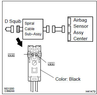
1 Check d squib circuit(airbag sensor assy center – horn button assy)
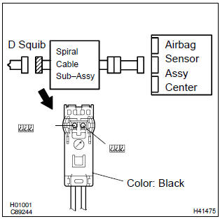
- Disconnect the negative (–) terminal cable from the battery, and wait at least for 90 seconds.
- disconnect the connectors between the airbag sensor assy center and the horn button assy.
- connect the negative (–) terminal cable to the battery, and wait at least for 2 seconds.
- turn the ignition switch to on.
- for the black connector (on the spiral cable sub–assy
side) between the horn button assy and the spiral cable
sub–assy, measure the voltage between d2+ and body
ground.
Ok: voltage: below 1 v


2 Check air bag sensor assy center
Sst 09843–18040
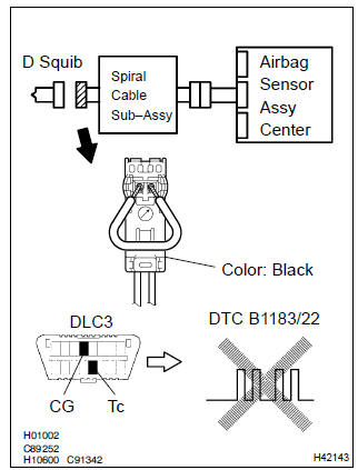
- Turn the ignition switch to lock.
- disconnect the negative (–) terminal cable from the battery, and wait at least for 90 seconds.
- connect the connector to the airbag sensor assy center.
- using a service wire, connect d2+ and d2– of the black connector (on the spiral cable sub–assy side) between the horn button assy and the spiral cable sub–assy.
- connect the negative (–) terminal cable to the battery, and wait at least for 2 seconds.
- turn the ignition switch to on, and wait at least for 20 seconds.
- clear the dtc stored in memory .
- turn the ignition switch to lock, and wait at least for 20 seconds.
- turn the ignition switch to on, and wait at least for 20 seconds.
- check the dtc .
Ok: dtc b1183/22 is not output.
Hint
: codes other than code b1183/22 may be output at this time, but they are not relevant to this check.


3 Check d squib
Sst 09843–18040
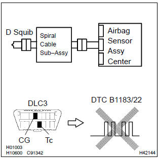
- Turn the ignition switch to lock.
- disconnect the negative (–) terminal cable from the battery, and wait at least for 90 seconds.
- connect the horn button assy connectors.
- connect the negative (–) terminal cable to the battery, and wait at least for 2 seconds.
- turn the ignition switch to on, and wait at least for 20 seconds.
- clear the dtc stored in memory .
- turn the ignition switch to lock, and wait at least for 20 seconds.
- turn the ignition switch to on, and wait at least for 20 seconds.
- check the dtc .
Ok: dtc b1183/22 is not output.
Hint
: codes other than code b1183/22 may be output at this time, but they are not relevant to this check.


4 Use simulation method to check


Replace all srs components including the wire harness
5 Check instrument panel wire(airbag sensor assy center – spiral cable sub–assy)
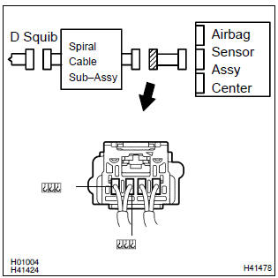
- Turn the ignition switch to lock.
- disconnect the connector of the instrument panel wire.
- turn the ignition switch to on.
- ) for the connector (on the spiral cable sub–assy side) between
the horn button assy and the spiral cable sub–assy,
measure the voltage between d2+ and body ground.
Ok: voltage: below 1 v

6 Check spiral cable sub–assy
- For the black connector (on the spiral cable sub–assy
side) between the horn button assy and the spiral cable
sub–assy, measure the voltage between d2+ and body
ground.
Ok: voltage: below 1 v


7 Use simulation method to check


Replace all srs components including the wire harness


Other materials:
Oxygen / af sensor heater monitor
Preconditions
The monitor will not run unless:
mil is off
drive pattern
connect the obd ii scan tool to the dlc3 to check monitor status
and preconditions.
Start the engine and allow it to idle for 9 minutes.
Drive the vehicle at 25 mph (40 km ...
Noise occurs
Inspection procedure
1 Check of speaker installation
Check speaker installation condition.
Check that each speaker is securely installed.
Standard: malfunction disappear.
Hint:
the radio is equipped with noise prevention system that does not work against
the regular use of t ...
Inspection
1. Cooling fan relay
Inspect the cooling fan relay continuity.
Using an ohmmeter, check that there is continuity
between terminals 1 and 2.
If there is no continuity, replace the relay.
Check that there is no continuity between terminals
3 and 5.
If there is conti ...