Toyota Corolla (E120) 2002–2008 Repair Manual / Diagnostics / Supplemental restraint system / Open in p squib circuit / Circuit description
Toyota Corolla (E120): Circuit description
1 Check p squib circuit(airbag sensor assy center – instrument panel passenger airbag assy)
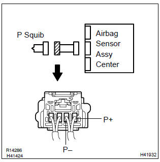
- Disconnect the negative (–) terminal cable from the battery, and wait at least for 90 seconds.
- disconnect the connectors between the airbag sensor assy center and the instrument panel passenger airbag assy.
- for the connector (on the instrument panel passenger airbag
assy side) between the airbag sensor assy center
and the instrument panel passenger airbag assy, measure
the resistance between p+ and p–.
Ok: resistance: below 1 Ω
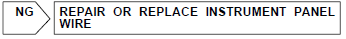

2 Check air bag sensor assy center
Sst 09843–18040
- Connect the connector to the airbag sensor assy center.
- using a service wire, connect p+ and p– of the connector (on the instrument panel passenger airbag assy side) between the airbag sensor assy center and the instrument panel passenger airbag assy.
- connect the negative (–) terminal cable to the battery, and wait at least for 2 seconds.
- turn the ignition switch to on, and wait at least for 20 seconds.
- clear the dtc stored in memory .
- turn the ignition switch to lock, and wait at least for 20 seconds.
- turn the ignition switch to on, and wait at least for 20 seconds.
- check the dtc .
Ok: dtc b0106/54 is not output.
Hint
: codes other than code b0106/54 may be output at this time, but they are not relevant to this check.


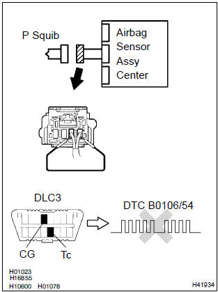
3 Check p squib
Sst 09843–18040
- Turn the ignition switch to lock.
- disconnect the negative (–) terminal cable from the battery, and wait at least for 90 seconds.
- connect the instrument panel passenger airbag assy connector.
- connect the negative (–) terminal cable to the battery, and wait at least for 2 seconds.
- turn the ignition switch to on, and wait at least for 20 seconds.
- clear the dtc stored in memory .
- turn the ignition switch to lock, and wait at least for 20 seconds.
- turn the ignition switch to on, and wait at least for 20 seconds.
- check the dtc .
Ok: dtc b0106/54 is not output.
Hint
: codes other than code b0106/54 may be output at this time, but they are not relevant to this check.

Use simulation method to check


Other materials:
Inspection procedure
Hint:
read freeze frame data using the hand-held tester or the obd ii scan tool.
Freeze frame data records the
engine conditions when a malfunction is detected. When troubleshooting, it is
useful for determining whether
the vehicle was running or stopped, the engine was warmed up or not, the ...
Ecm/pcm processor
Dtc p0606 ecm/pcm processor
Monitor description
The ecm continuously monitors its internal circuits. This self–check insures
that the ecm is functioning properly.
If a malfunction is detected, the ecm will set the appropriate dtc and
illuminate the mil.
The two cpus, main and sub cpu i ...
The ambient temperature does not display
Wiring diagram
Inspection procedure
1 Inspect outer ambient temperature sensor
Remove cooler (ambient temp. Sensor) thermistor.
measure resistance between terminals 1 and 2 of cooler
(ambient temp. Sensor) thermistor connector at each temperature.
Resistance:
at 0 c (0 f) ...