Toyota Corolla (E120) 2002–2008 Repair Manual / Diagnostics / Sfi system / Fuel pump control circuit / Circuit description
Toyota Corolla (E120): Circuit description
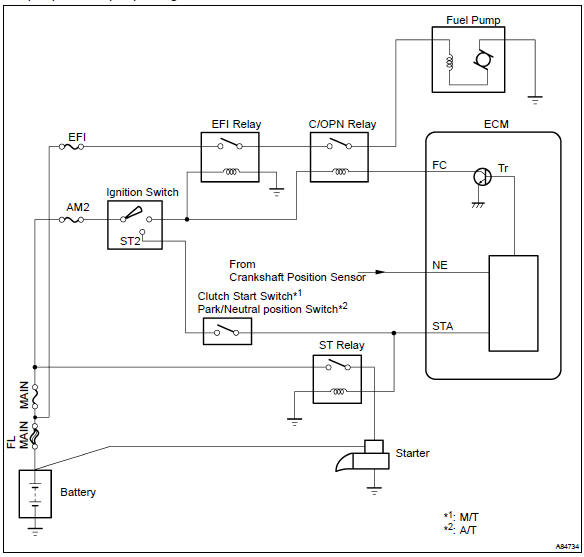
In the diagram below, when the engine is cranked, current flows from terminal st2 of the ignition switch to the starter relay coil and also current flows to terminal sta of the ecm (sta signal).
When the sta signal and ne signal are input to the ecm, tr is turned on, current flows to the coil of the circuit opening relay, the relay switches on, power is supplied to the fuel pump and the fuel pump operates.
While the ne signal is generated (engine running), the ecm keeps tr on (circuit opening relay on) and the fuel pump also keeps operating.
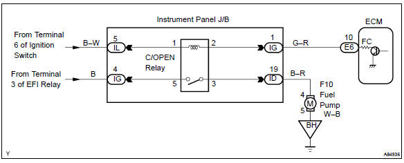
Wiring diagram


Other materials:
What to do if... (Troubleshooting)
If you have a problem, check the following before contacting your Toyota dealer.
The doors cannot be locked, unlocked, opened or closed
You lose your keys
● If you lose your keys or mechanical keys, new genuine keys or mechanical keys
can be made by your Toyota dealer.
● If you lo ...
Parking the vehicle
► Automatic transmission or continuously
variable transmission Automatic transmission or continuously variable transmission
1 With the shift lever in D, depress the brake pedal.
2 Shift the shift lever to P.
3 Set the parking brake.
4 Vehicles without a smart key system: Turn ...
Replacement
1. Remove front door scuff plate rh
Using a screwdriver, remove the front door scuff plate rh.
Hint:
tape the screwdriver tip before use.
Remove front door scuff plate lh
Remove rear door scuff plate rh
Using a screwdriver, remove the rear door scuff plate rh.
Hint:
tap ...