Toyota Corolla (E120) 2002–2008 Repair Manual / Diagnostics / Sfi system / Knock sensor 1 circuit / Circuit description
Toyota Corolla (E120): Circuit description
A flat type knock sensor (non–resonant type) has the structure that can detect the vibration in a wider band of frequency from about 6 khz to 15 khz and has the following features.
Knock sensors are fitted on the cylinder block to detect the engine knocking.
The sensor contains a piezoelectric element which generates a voltage when it becomes deformed, which occurs when the cylinder block vibrates due to knocking. If engine knocking occurs, the ignition timing is retarded to suppress it.
Hint
: if the ecm detects the dtc p0325, it enters the fail–safe mode in which the corrective retarded angle value is set to the maximum value.
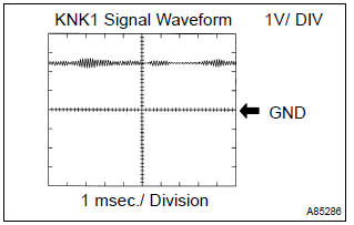
Reference: inspection using the oscilloscope.
- After warming up run the engine at 4,000 rpm, check the waveform between terminal knk1 and eknk of the ecm connector.
Monitor description
The knock sensor, located on the cylinder block, detects spark knock. When spark knock occurs, the sensor picks–up vibrates in a specific frequency range. When the ecm detects the voltage in this frequency range, it retards the ignition timing to suppress the spark knock.
The ecm also senses background engine noise with the knock sensor and uses this noise to check for faults in the sensor. If the knock sensor signal level is too low for more than 10 seconds, and if the knock sensor output voltage is out of normal range, the ecm interprets this as a fault in the knock sensor and sets a dtc.
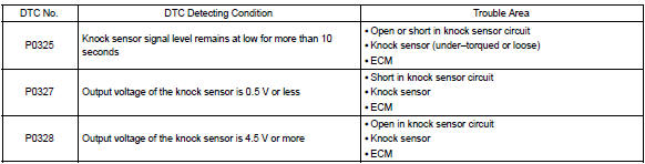
Monitor strategy
Typical enabling conditions
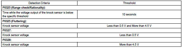
Typical malfunction thresholds
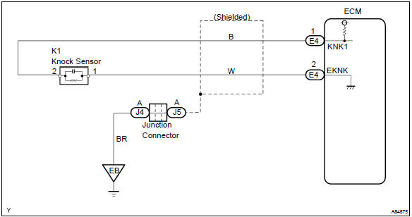
Wiring diagram


Other materials:
Inspection procedure
1 Check p/t squib(rh) circuit(airbag sensor assy center – front
seat outer belt assy rh)
Disconnect the negative (–) terminal cable from the battery,
and wait at least for 90 seconds.
disconnect the connectors between the airbag sensor
assy center and the seat belt pretensio ...
Inspection procedure
Hint:
if different dtcs related to different systems that have terminal e2
as the ground terminal are output
simultaneously, terminal e2 may be open.
Read freeze frame data using the hand-held tester or the obd ii scan
tool. Freeze frame data records
the engine conditions when a malf ...
Setup menu
You can adjust the multimedia system to your desired settings.
Display “Setup” screen
Press the “SETUP” button to display the “Setup” screen.
1 Select to adjust the settings for operation sounds, screen animation, etc.
2 Select to set the voice settings.
3 Select to adjust the s ...