Toyota Corolla (E120) 2002–2008 Repair Manual / Diagnostics / Sfi system / Oxygen sensor circuit slow
response / Circuit description
Toyota Corolla (E120): Circuit description
Refer to dtc p0130
|
Dtc no. |
Dtc detection condition |
Trouble area |
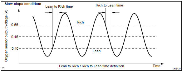
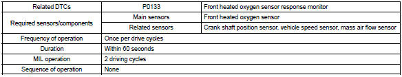
| P0133 | After engine has been warmed up, if response time that heated
oxygen sensor’s output voltage reaches from rich to lean. Or from lean to rich, is 0.6 Second or more during idling. (2 Trip detection logic) |
|
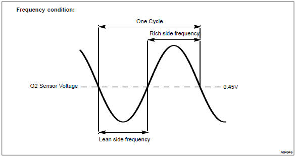
| If response time of heated oxygen sensor’s output voltage in one rich–lean cycle is 6 seconds or more during idling. (2 Trip detection logic) |
Hint
: sensor 1 refers to the sensor closest to the engine assembly.
Monitor description
The engine control module (ecm) uses the heated oxygen sensor information to regulate the air–fuel ratio close to a stoichiometric ratio. This maximizes the catalytic converter’s ability to purify the exhaust gases.
The sensor detects oxygen levels in the exhaust gas and sends this signal to the ecm.
The inner surface of the sensor element is exposed to the outside air. The outer surface of the sensor element is exposed to the exhaust gas. The sensor element is made of the platinum coated zirconia and includes an integrated heating element. The heated oxygen sensor has the characteristic whereby its output voltage change suddenly in the vicinity of the stoichiometric air–fuel ratio. The heated oxygen sensor generates waveform of a voltage between 0 v and 1 v in response to the oxygen concentration in exhaust gas.
When the output voltage of the heated oxygen sensor is 0.55 V or more, the ecm judges that the air–fuel ratio is rich. When it is 0.40 V or less, the ecm judges that the air–fuel ratio is lean.
The ecm monitors the response feature of the heated oxygen sensor. If the response time of the sensor output status change from rich to lean or vice versa becomes longer, the ecm interprets this as a malfunction in the heated oxygen sensor and sets a dtc.
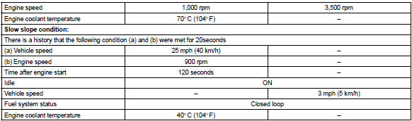
Monitor strategy
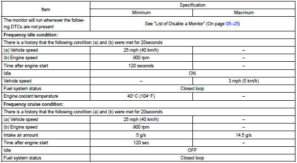
Typical enabling condition
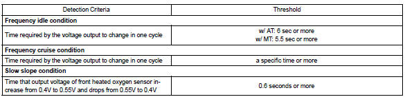
Typical malfunction thresholds
Component operating range

Wiring diagram
Refer to dtc p0130


Other materials:
Inspection procedure
1 Check side squib(lh) circuit(airbag sensor assy center – front
seat airbag assy lh)
Disconnect the negative (–) terminal cable from the battery,
and wait at least for 90 seconds.
disconnect the connectors between the airbag sensor
assy center and the front seat airbag assy ...
Precaution
1. Notices when checking
power door lock/unlock function:
the wireless remote control function operates only when the following 3
conditions are met.
No key is inserted into the ignition key cylinder.
All the doors are closed. However, doors can be unlocked even wh ...
If the vehicle is submerged or
water on the road is rising
This vehicle is not designed
to be able to drive on roads
that are deeply flooded with
water. Do not drive on roads
where the roads may be
submerged or the water
may be rising. It is dangerous
to remain in the vehicle,
if it is anticipated that the
vehicle will be flooded or
set adrift. Remain calm ...