Toyota Corolla (E120) 2002–2008 Repair Manual / Diagnostics / Sfi system / Camshaft position ”a” actuator
circuit / Circuit description
Toyota Corolla (E120): Circuit description
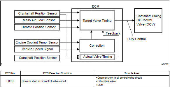
The variable valve timing (vvt) system includes the ecm, the oil control valve (ocv) and the vvt controller.
The ecm sends a target ”duty–cycle” control signal to the ocv. This control signal, applied to the ocv, regulates the oil pressure supplied to the vvt controller. Camshaft timing control is performed based on engine operation conditions such as the intake air volume, throttle position and engine coolant temperature.
The ecm controls the ocv, based on the signals output from the sensors. The vvt controller regulates the intake camshaft angle using oil pressure through the ocv. As result, the relative position between the camshaft and the crankshaft is optimized, and the engine torque improves, fuel economy improves, and exhaust emissions decrease under overall driving conditions. Also, the ecm detects the actual valve timing using signals from the camshaft position sensor and the crankshaft position sensor, and performs the feedback control. This is how target valve timing is verified by the ecm.
Monitor description
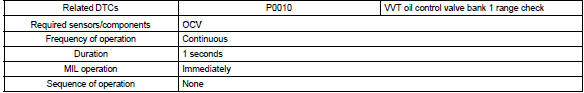
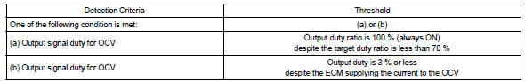
After the ecm sends the ”target” duty–cycle signal to the ocv, the ecm monitors the ocv current to establish an ”actual” duty–cycle. The ecm detects a malfunction and sets a dtc when the actual duty–cycle ratio varies from the target duty–cycle ratio.
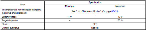
Monitor strategy
Typical enabling conditions
Typical malfunction thresholds
Component operating ra

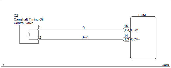
Wiring diagram


Other materials:
Replacement
1. Drain brake fluid
Notice:
wash the brake fluid off immediately if it comes into contact with any painted
surface.
2. Remove front wheel rh
3. Remove front fender liner rh
4. Remove brake actuator with bracket
turn the latch of the actuator connector to disconnect the
connector. ...
Purpose of the readiness tests
The on–board diagnostic (obd ii) system is designed to monitor the
performance of emission–related
components and report any detected abnormalities in the form of diagnostic
trouble codes
(dtcs). Since the various components need to be monitored during different
driving condition ...
Source voltage drop
The srs is equipped with a voltage–increase circuit (dc–dc converter) in the
airbag sensor assy center
in case the source voltage drops.
When the battery voltage drops, the voltage–increase circuit (dc–dc converter)
functions to increase the
voltage of the srs to normal voltage.
...