
Toyota Corolla (E120): Checking monitor status
Hint
: ”monitor result” indicates normal or malfunction of each component and system when judgment has done.
1. How to read data
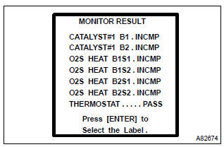
- Connect the hand–held tester to the dlc 3.
- enter ”monitor result” from ”diagnosis / enhanced obd ii / monitor info / monitor result” on the hand–held tester. You will see ”test id” and ”incmp”, ”pass” or ”fail” on the monitor result screen.
Hint
:
- incmp: the judgement has not been done yet.
- Pass: normal is detected.
- Fail: malfunction is detected.
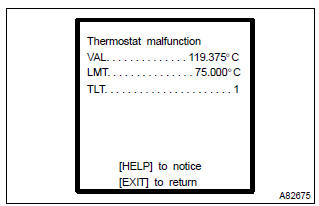
- Select a test id that you want from the list and press the ”enter” button. You will see the following screen:
- val (test value) [test data] [unit]
- lmt (test limit) [test limit] [unit]
- tlt [test limit type]
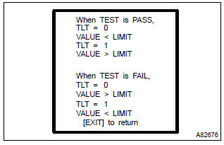
- By pressing the ”help” button, you can see more information.
Hint
:
- monitor test results can be viewed in the monitor result screen.
- Monitor test results indicate the latest malfunction judgement result of this diagnostic.
- Test value indicates the detection parameter value (example: p0128 thermostat malfunction = engine coolant temperature) at the time of malfunction (or normal) judgement is done.
- Test limit indicates a threshold of malfunction judgement (example: p0128 thermostat malfunction = 75 c).
- When the monitor runs, the monitored parameter’s value is recorded. The value is then compared to the test limit to determine if the result is pass or fail.
- By comparing the parameter value to the test limit, it is possible to determine the degree of failure.
- In rare cases, the monitor may have passed even with a dtc set and mil illuminated. The monitor may have failed on a previous trip, and then passed on the most recent trip. This would indicated an intermittent problem may be the cause of the dtc.


Other materials:
On–vehicle inspection
1. Check cooling fan operation with low temperature (below 83 c (181 f))
Turn the ignition switch on.
check that the cooling fan stops.
Hint:
if not, check the cooling fan relay and water temperature sensor, and check for
separated connector or severed
wire between the cooling fan ...
Safety Connect services
■ Automatic Collision Notification
In case of either airbag deployment
or severe rear-end collision,
the system is designed to
automatically call the response
center. The responding agent
receives the vehicle's location
and attempts to speak with the vehicle occupants to assess the
level of emerge ...
License plate lamp assy
Replacement
1. Remove luggage compartment lock cylinder & key set
2. Remove luggage compartment door garnish outside
3. Remove license plate lamp assy
Pull the license plate light assy to the side of vehicle as
shown in the illustration and release the claw.
disconnect the c ...