Toyota Corolla (E120): Pre–check
1. Selecting compass display mode
- the compass switch allows you to select the display or non–display mode of the compass.
2. Setting zone
- deviation between the ”magnetic north” and ”actual north” differs depending on the location. Therefore, adjustment of the magnetism is required. Since the magnetic condition differs according to the area where the vehicle is used, it is necessary for each user to set the zone (refer to ”compass zone map”). The zone setting can be changed using the comp switch of the inner mirror.
3. Performing calibration
- because each vehicle has its own magnetic field, calibration
should be performed for each vehicle.
This compass function is used when storing the record of the vehicle’s magnetic field.
4. When compass magnetized:
- a compass could be magnetized during shipping by vessels or freight cars. Before delivery, therefore, make sure to perform calibration and ensure that calibration is done properly. If it cannot be done (cannot be complete in spite of driving around several times), it may be caused by magnetization. Demagnetize the vehicle using a demagnetizer and perform calibration again.
5. Setting compass
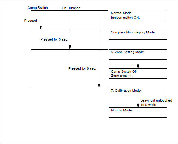
6. Zone setting mode
- pressing the comp switch for 3 seconds, in the normal mode, will
activate the zone setting mode.
A number (1 – 15) is displayed on the compass display.
Hint
: in the initial state, ”8” is displayed.
- the displayed number increases +1 every time the comp switch is pressed. Referring to the map, check the number for the area where the vehicle will be used and set the zone number.
- leave it untouched for several seconds after setting and check that the compass display shows an azimuthal direction (n, ne, e, se, s, sw, w or nw) or ”c”.
7. Calibration setting mode
- pressing the comp switch for 6 seconds, in the normal mode, will also activate this mode.
- drive the vehicle at a slow speed of 8 km/h (5 mph) or less in the circular direction.
- driving around the circle 1 to 3 times will display the azimuthal direction on the display, completing the calibration.
Hint
: once calibration is complete, it is not necessary to perform the above procedures unless the magnetic field strength is drastically changed. If this happens, the azimuthal display will be changed to ”c”.


Other materials:
Under hood
General maintenance
1. General notes
maintenance requirements vary depending on the country.
Check the maintenance schedule in the owner’s manual supplement.
Following the maintenance schedule is mandatory.
Determine the appropriate time to service the vehicle using either miles
driv ...
Using the dynamic radar
cruise control
Setting the vehicle speed
1. Press the driving assist mode
select switch to select
dynamic radar cruise control.
The dynamic radar cruise control
indicator will illuminate.
2. Using the accelerator pedal,
accelerate or decelerate to
the desired vehicle speed
(approximately 20 mph [30
km/h] or more ...
Disposal
1. Dispose shock absorber assy front lh
fully extend the shock absorber piston rod.
using a drill, make a hole in the cylinder as shown in the
illustration to discharge the gas inside.
Caution:
when drilling, chips may fly out, work carefully.
The gas is colorless, o ...