Toyota Corolla (E120) 2002–2008 Repair Manual / Introduction / Repair instruction / Precaution / Electronic control
Toyota Corolla (E120): Electronic control
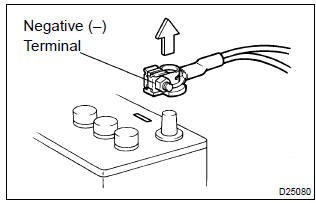
- Removal and installation of battery terminal
- before performing electrical work, disconnect the battery negative (–) terminal cable beforehand so as to prevent burnt–out damage by short.
- When disconnecting and installing the terminal cable, turn the ignition switch and lighting switch off, and loosen the terminal nut completely. Perform these operations without twisting or prying the terminal.
- When the battery terminal is removed, all the memories
of the clock, radio, dtcs, etc. Will be erased.
So before removing it, check them and note them down.
- Handling of electronic parts
- do not open the cover or case of the ecu unless absolutely necessary (if the ic terminals are touched, the ic may be destroyed by static electricity).
- To disconnect electronic connectors, pull the connector itself, not the wires.
- Be careful not to drop electronic components, such as sensors or relays. If they are dropped on a hard floor, they should be replaced and not be reused.
- When cleaning the engine with steam, protect the electronic components, air filter and emission–related components from water.
- Never use an impact wrench to remove or install temperature switches or temperature sensors.
- When checking the continuity at the wire connector, insert the tester probe carefully to prevent terminals from bending.


Other materials:
Circuit description
The airbag front rh sensor circuit consists of the airbag sensor assy center
and airbag front rh sensor.
Dtc b1156/b1157/15 is recorded when a malfunction is detected in the airbag
front rh sensor circuit.
Wiring diagram
...
Displaying the device status
Select “Bluetooth* info” using .
● Displaying the device name
Select “Device Name” using .
● Displaying the device address
Select “Device Address” using .
*: Bluetooth is a registered trademark of Bluetooth SIG, Inc. ...
Outside temperature display
The temperature display shows temperatures within the range of -40°F (-40°C)
to 122°F (50°C).
► Type A
► Type B
► Type C
► Type D
■The outside temperature is displayed when
►Vehicles without a smart key system
The engine switch is in the “ON ...