Toyota Corolla (E120) 2002–2008 Repair Manual / Diagnostics / Wireless door lock control system / Terminals of ecu
Toyota Corolla (E120): Terminals of ecu
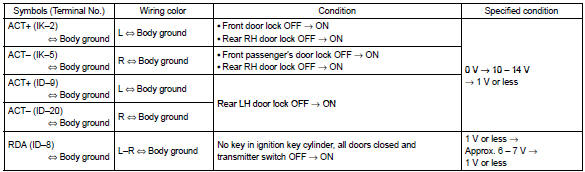
1. Inspect integration relay
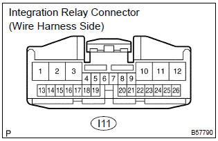
- Disconnect the connector from the integration relay.
- check the continuity between each terminal of the disconnected connector and the body ground, as shown in the illustration and table.
Standard:
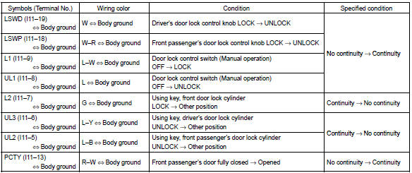
If the result is not as specified, the vehicle’s side may malfunction.
- reconnect the connector and check the voltage between each terminal and the body ground, as shown in the illustration and table.
Standard:
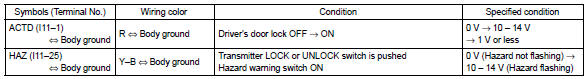
If the result is not as specified, the integration relay may malfunction.
2. Inspect instrumental panel j/b (integration relay)
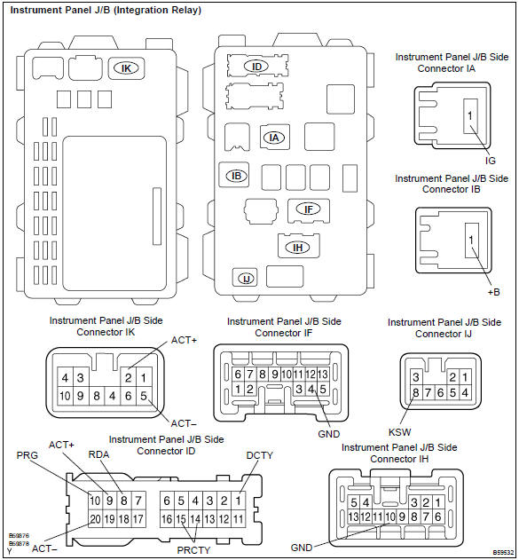
- Disconnect the connectors ia, ib, id, if, ih and ij of the instrument panel j/b.
- check the continuity between each terminal of the disconnected connectors and the body ground, as shown in the illustration and table.
Standard:
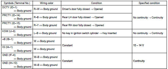
If the result is not as specified, the vehicle’s side may malfunction.
- reconnect the connectors and check the voltage between each terminal and the body ground, as shown in the illustration and table.
Standard:
If the result is not as specified, the integration relay or instrument panel j/b assembly may malfunction.
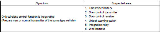
Problem symptoms table


Other materials:
Starting system
Inspection
1. Inspect starter assy
Notice:
these tests must be performed within 3 to 5 seconds to
prevent burnout of the coil.
perform the pull–in test.
Remove the nut, then disconnect the lead wire from
terminal c.
Connect the battery to the starter repai ...
Emission inspection and maintenance (I/M) programs
Some states have vehicle emission inspection programs which include OBD (On
Board Diagnostics) checks. The OBD system monitors the operation of the emission
control system.
If the malfunction indicator lamp comes on
The OBD system determines that a problem exists somewhere in the emission cont ...
Inspection procedure
Hint:
the switch described in this text is a switch for transmitting signals which is
built in the door control transmitter.
1 Check wireless door lock control functions
Normal
2 Replace transmitter battery with normal one
After replacing the transmitter battery with a new or normal o ...